Build a Tiny Arduino FPV Drone from Scratch
Summary
Have you ever wanted to build your own FPV drone but thought it required expensive, specialized components?
Well, in this comprehensive guide, we'll walk through creating a fully functional, 30-gram Arduino-powered FPV drone using common electronic components and simple materials like popsicle sticks.
This miniature racing drone features live video transmission, custom Arduino flight controller, and can be controlled via a homemade transmitter.
Best of all, it's designed to be built on a budget while providing excellent learning experience in drone mechanics, electronics, and programming.

Step-by-Step Guide to Build a Arduino FPV Drone
Components Needed
Flight System:
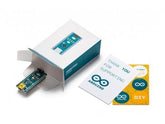
- (1x) Arduino Pro Mini (5V 16MHz)
- (1x) MPU6050 6-axis gyroscope/accelerometer sensor
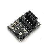
- (1x) NRF24L01 transceiver module
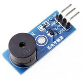
- (1x) 5V passive buzzer
Motor System:
- (4x) 6mm coreless brushed motors
- (4x) Small propellers (31mm diameter, 4-blade)
- (4x) SMD MOSFET transistors (SI2300)
- (4x) SMD resistors (10kΩ)
- (4x) SMD diodes (1N4148 Schottky flyback diodes)
Power & Electronics:
- (1x) 3.7V 220mAh LiPo battery
- (1x) JST connector
- 24AWG and 30AWG wires
- Perforated circuit board
- Copper sheet (30x18mm) for EMF shielding
Frame Materials:
- (4x) Popsicle sticks
- (1x) Rubber band for battery mounting
- (4x) Zip ties
- Bicycle inner tube rubber for bumpers
- PVC glue and superglue
FPV System:
- (1x) 3G 600TVL FPV camera with built-in transmitter
- FPV goggles for viewing
Transmitter Components
- (1x) Arduino Nano
- (1x) NRF24L01 transceiver (long antenna version)
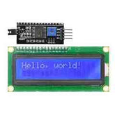
- (1x) 16x2 LCD with I2C
- (2x) Joystick module
- (2x) 3-pin toggle switch
- (1x) 100kΩ potentiometer
- (1x) 7.4V 2S battery
- 3D printed enclosure
Step 1: Frame Construction
Popsicle Stick Method
Cutting and Shaping:
Start by creating a template for your drone frame pieces. The design should resemble a miniature quadcopter with four arms extending from a central body. Cut your popsicle sticks according to the template, using a sharp hobby knife for precision.

Assembly Process:
- Glue the frame pieces together using PVC glue, ensuring perfect alignment
- Add a slightly angled front piece for optimal camera mounting
- Drill small holes for the power connector
- Create bumper strips from bicycle inner tube rubber to protect vulnerable areas
- Reinforce critical stress points with additional superglue
This is what it should look like:

Alternative: 3D Printing
If you prefer precision over DIY charm, design and print a custom frame. This saves significant time and ensures perfect repeatability, though it may be slightly heavier than the wooden alternative
Step 2: Custom Motor Driver Board
This is one of the most critical components of your drone. Since we're using an Arduino with limited current output, we need MOSFETs to properly drive our motors.
Safety First: Always wear an ESD wrist strap when handling MOSFETs, as static electricity can permanently damage these sensitive components.
Board Construction:
- Layout planning: Arrange four identical circuits on your perforated board, each containing one MOSFET, one resistor, and one diode
- Soldering sequence: Start with MOSFETs, followed by Schottky flyback diodes, then 10kΩ pull-down resistors
- Power distribution: Create clean ground and power lines connecting all circuits
- Weight optimization: Trim excess board material and sand smooth - target under 1-gram total weight
- Circuit Function: Each MOSFET acts as a switch controlled by the Arduino's PWM signals, while the flyback diodes protect against voltage spikes when motors stop, and pull-down resistors ensure MOSFETs stay off when not actively driven.

Step 3: Motor Integration
Motor Selection Critical: Choose motors with adequate thrust-to-weight ratio. For a 30-gram drone, you need motors producing at least 14 grams of thrust each, giving you 56 grams total thrust for proper maneuverability.
Installation Process:
- Secure mounting: Use superglue to attach motors to frame arms - this is permanent, so ensure perfect alignment
- Direction planning: Two motors spin clockwise, two counter-clockwise (you can adjust this in software)

- Driver board placement: Mount your custom motor driver in the frame's central cavity
- Landing gear: Install zip ties pointing downward for both landing feet and wire management
- Wiring Strategy: Connect motors directly to the flyback diodes, maintaining consistent polarity. Keep all connections as short as possible to minimize electrical interference.
Step 4: Electronics Integration
4.1 Flight Control System
- Arduino Setup: Use the 3.3V version of the Arduino Pro Mini for optimal LiPo battery compatibility. This eliminates voltage regulation issues and improves power efficiency.
- Sensor Integration: Mount the MPU6050 gyroscope/accelerometer using minimal connections - just power and I2C communication lines. This sensor provides crucial orientation data for flight stability.

Radio Communication
- NRF24L01 Preparation: Remove the pin headers to save weight and replace with direct wire connections. Mount the module in the frame's rear section for optimal antenna positioning.
- Interference Prevention: Seal all exposed connections with Kapton tape to prevent short circuits, especially important given the compact layout.
Power Distribution Strategy
- Smart Power Routing: Connect the NRF24L01 to the gyroscope module's 3.3V regulator rather than directly to the battery. The regulator includes filtering capacitors that help reduce electrical noise - crucial for stable operation.
- Ground Management: Establish a solid ground plane throughout the drone to minimize electromagnetic interference between components.
Step 5: Programming and Configuration
Firmware Installation
Your drone requires custom firmware based on MultiWii, specifically adapted for this hardware configuration. The code handles:
- Sensor data processing: Converting gyroscope readings into flight corrections
- Motor control: PWM generation for speed control
- Radio communication: Receiving commands from your transmitter
- Safety features: Automatic disarming and status indication
Programming Process:
- Connect your drone to a computer via FTDI converter
- Configure Arduino IDE with correct board settings (Arduino Pro Mini, appropriate voltage)
- Upload firmware using the standard Arduino process
- Verify successful upload by checking for proper LED behavior
MultiWii Configuration
- MultiWii software provides essential setup and tuning capabilities:
Initial Setup:
- Establish communication with your drone
- Verify all sensor readings are correct
- Test radio channel assignments
- Configure safety switches (arming, beeper)
Switch Configuration:
- AUX1 Channel: Drone arming/disarming
- AUX2 Channel: Beeper activation for locating crashed drones
Step 6: Final Assembly and Testing
Physical Completion
Component Integration:
- Install FPV camera in front position, angled slightly upward
- Wire camera directly to battery power for best performance
- Secure all wiring with zip ties or heat shrink tubing
- Create battery mounting system using rubber band "pocket"
Weight Verification: Your completed drone should weigh approximately 30 grams. If significantly heavier, review all components for weight reduction opportunities.
Pre-flight Setup
Power-on Sequence:
- Place the drone on perfectly flat surface
- Power on the drone first, then the transmitter
- Perform gyroscope calibration using transmitter stick movements
- Wait for initialization complete signal
- Arm drone and test the motor response
Flight Tuning
- PID Adjustment: Connect to MultiWii software for fine-tuning:
- P (Proportional) values: Gradually reduce roll and pitch P values until oscillations disappear
- Rate settings: Lower rate values for gentler response
- Expo values: Increase expo for smoother control curves around the center stick
Flight Testing Protocol
Indoor Validation
Start with careful indoor hover tests in a large, open room. This allows you to:
- Verify basic stability
- Test control responsiveness
- Identify any remaining oscillation issues
- Practice basic maneuvers safely
Outdoor Flying
Once indoor performance is satisfactory:
- Choose calm weather conditions (minimal wind)
- Select open areas away from people and property
- Start with gentle, low-altitude flights
- Gradually increase complexity as confidence builds
FPV Experience
- Connect your 5.8GHz FPV goggles to experience true first-person flight. The 600TVL camera provides adequate resolution for navigation and immersive flying experience.
Performance Expectations
Your completed drone will offer:
- Stable hovering: Proper tuning enables hands-off stability
- Agile maneuvering: Low weight provides excellent power-to-weight ratio
- Indoor flying capability: Perfect for year-round practice and fun
- Learning platform: Excellent foundation for understanding drone mechanics
Conclusion
Building an Arduino FPV drone from scratch provides invaluable hands-on experience with electronics, programming, and mechanical design.
While challenging, the project is entirely achievable with patience, attention to detail, and systematic problem-solving.
The 30-gram result proves that impressive performance doesn't require expensive, proprietary components.
With basic Arduino modules, careful construction, and proper tuning, you can create a fully functional FPV racing drone that rivals commercial alternatives.


