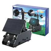
QE011 ACEBOTT Weather Station Starter Kit Assembly Guide
Summary
The QE011 ACEBOTT Weather Station is an ESP32-based educational kit that combines multiple sensors with wireless connectivity to create a comprehensive environmental monitoring system.
It's designed to bridge the gap between learning and practical application, making it perfect for students, educators, and hobbyists who want to get hands-on with IoT technology.
But does this kit live up to its educational promise? In this walkthrough, we'll unpack the components, examine the technical specifications, and guide you through the complete assembly process.
Let's discover if the QE011 ACEBOTT Weather Station has what it takes to be your gateway into the world of connected environmental monitoring.

What is the QE011 ACEBOTT Weather Station Starter Kit?
It's a comprehensive STEM weather station kit that combines multiple environmental sensors with ESP32 microcontroller technology to create a fully functional weather monitoring system.
This isn't just another basic sensor kit – it's a complete educational platform designed to teach real-world IoT applications while producing genuinely useful data.
What makes this kit unique is its combination of professional-grade sensors with beginner-friendly assembly instructions, making it accessible to students while still being sophisticated enough for advanced projects.
The STEM kit comes with everything needed to measure temperature, humidity, atmospheric pressure, wind speed, wind direction, and rainfall – essentially creating a miniature version of professional meteorological equipment.
This ACEBOTT weather station kit assembly is positioned as both an educational tool and a practical device.
Unlike simple sensor modules that only teach basic concepts, the QE011 provides a complete ecosystem for learning about data collection, wireless transmission, cloud connectivity, and real-time monitoring.
It's designed to give users a comprehensive understanding of how modern weather stations actually work, from sensor integration to data visualization.
Hardware Components and Features
Let's dive into the hardware. The QE011 ACEBOTT Weather Station comes packed with an impressive array of components that work together to create a sophisticated monitoring system.
1. ESP32 Microcontroller Board: At the heart of the system is the ESP32, a powerful dual-core processor with built-in Wi-Fi and Bluetooth capabilities. It's a full IoT platform that can handle complex data processing, wireless communication, and real-time operations simultaneously.
2. Comprehensive Sensor Array: The kit includes multiple high-quality sensors for complete environmental monitoring:
- DHT22 temperature and humidity sensor for accurate atmospheric readings
- BMP280 barometric pressure sensor for weather prediction capabilities
- Anemometer for wind speed measurement with hall effect sensor technology
- Wind vane for directional wind monitoring with analog output
- Rain gauge with tipping bucket mechanism for precipitation measurement
3. Weather-Resistant Housing: Understanding that outdoor deployment is essential for accurate readings, the kit includes weatherproof enclosures designed to protect sensitive electronics while allowing proper airflow for sensors. The housing is UV-resistant and designed to withstand various weather conditions.
4. Display and Interface Components: A clear OLED display provides real-time local readings, while LED indicators show system status and connectivity. The kit also includes buttons for manual interaction and configuration.
5. Power Management System: The IoT weather station build guide wouldn't be complete without addressing power. The kit includes options for both AC adapter and battery operation, with solar panel compatibility for truly autonomous operation.
Smart power management ensures extended battery life during outdoor deployments.
Step-by-Step Assembly Guide
Now comes the exciting part, which is, putting it all together. The QE011 ACEBOTT weather station assembly process is designed to be educational while remaining manageable for beginners. Here's your complete walkthrough:
Phase 1: Initial Preparation and Component Verification
Step 1: Unpack and Inventory Components
Take all parts out of the package carefully and lay them out on a clean, well-lit workspace. Check each component against the provided parts list to ensure nothing is missing.
Step 2: Prepare Acrylic Components
Remove all protective paper attached to the acrylic panels. This step is crucial as leaving the protective film on can affect the final appearance and functionality of your ESP32 weather station DIY project. Peel off the paper carefully to avoid scratching the acrylic surface.
Phase 2: Critical Pre-Assembly - Servo Initialization
(Important: Before beginning physical assembly, you must initialize the servo motor to prevent damage during installation.)
Step 3: Prepare ESP32 Controller Board
Connect your ESP32 controller board to your computer via USB cable. You'll need to upload the initialization program to the ESP32 before connecting any components.
Step 4: Upload Servo Initialization Program
Upload the servo initialization program to the ESP32 controller board. (Note: The specific programming steps are covered in the tutorial lessons - refer to the complete tutorial documentation available at acebott.com/tutorial/)
Step 5: Connect Servo for Initialization
Connect the servo motor line to pin 4 of the ESP32 controller board. Critical wiring note: The brown line connects to Ground (G), and the red line connects to VCC (D). The signal wire (typically orange or yellow) connects to the digital pin 4.
Step 6: Initialize Servo Position
Turn on the power switch. The servo motor will automatically move to its initialized angle position. This step ensures the servo starts from a known reference point, which is essential for accurate wind direction measurements later.
Phase 3: Power System Assembly
Step 7: Install Battery Box
(Critical Warning: Pay special attention to the direction of the battery box installation. Do NOT install the battery box in reverse orientation, as this can damage the charging circuit and controller board.)
Position the battery box according to the orientation markings on the housing. The positive and negative terminals should align with the corresponding markings on the mounting area.
Step 8: Connect Battery Charging System
Connect the terminal wires from the battery holder to the charging module. Ensure secure connections - loose connections can cause power interruption during operation. The charging module regulates power from both battery and solar panel inputs.
Phase 4: Sensor Installation and Mounting
Step 9: Install Environmental Sensors
(Orientation Critical: Note that the orientation of each sensor is crucial for proper operation. Install sensors with their terminals facing upward to ensure proper electrical connections and environmental exposure.)
Mount each sensor in its designated location within the weather housing:
- DHT11 temperature/humidity sensor
- Atmospheric pressure sensor (BMP280/BME280)
- UV sensor
- Light sensor
- Raindrop sensor
- PM2.5 particulate matter sensor
Step 10: Install Side Plates and Structural Components
Install the side plates with careful attention to orientation. Note: The short side should be positioned on top. This ensures proper ventilation and weather protection for the internal components.
Secure all mounting screws finger-tight initially, then tighten with appropriate tools once all components are positioned correctly.
Phase 5: Servo and Solar Panel Integration
Step 11: Mount Servo Motor in Housing
Install the servo motor with the motor shaft facing upward initially, then rotate the housing so the motor shaft faces outward. This orientation allows the solar panel to track the sun's movement throughout the day for optimal power generation.
Step 12: Install Solar Panel Tracking System
Load the solar panel horizontally into the servo motor mounting system. Alignment Critical: Ensure the two depressions on the solar panel mount align perfectly with the corresponding features on the servo motor shaft. Misalignment will cause binding and potential damage to the tracking mechanism.
The solar panel should move smoothly when the servo operates. Test the movement range before final assembly to ensure no obstructions interfere with tracking.
Phase 6: Wind Measurement System Assembly
Step 13: Install Anemometer
Mount the anemometer (wind speed sensor) in its designated position. Wire Management: Let the anemometer wire pass through the threading hole provided in the housing. This prevents wire stress and ensures weather-tight sealing.
The anemometer should spin freely without any friction or obstruction. Test rotation by hand to verify smooth operation before proceeding.
Step 14: Install Wind Vane
Mount the wind direction sensor (wind vane) ensuring it can rotate 360 degrees without obstruction. The vane should be balanced and respond to gentle air currents.
Phase 7: Complete Electrical Connections
(Critical Safety Warning: Ensure that all cables are correctly connected before powering on the device to avoid burning the modules and controller board. Double-check all connections against the wiring diagram.)
Step 15: Primary Sensor Connections
Following the ACEBOTT assembly instructions, connect each sensor to its designated ESP32 pin:
Servo Motor Connection:
- Connect to pin 4
- Brown line connects to Ground (G)
- Red line connects to VCC (D)
- Signal wire to digital pin 4
Environmental Sensor Connections:
- Vibration sensor: Connect to analog pin A0
- DHT11 sensor (temperature/humidity): Connect to digital pin 23
- Anemometer: Connect to digital pin 32
- UV sensor: Connect to analog pin 33
- Light sensor: Connect to analog pin 36
- Raindrop sensor: Connect to analog pin 39
Advanced Sensor Connections:
- PM2.5 sensor: Connect to pins 16 and 17 (UART communication)
- Atmospheric pressure sensor: Connect to I2C bus (SDA/SCL pins)
- OLED display module: Connect to I2C bus (shared with pressure sensor)
Step 16: I2C Bus Configuration
The atmospheric pressure sensor and OLED display module both use the I2C communication protocol. Connect both devices to the same I2C bus:
- SDA (data line) typically connects to pin 21
- SCL (clock line) typically connects to pin 22
- Both devices also need VCC and Ground connections
Step 17: Power Distribution Verification
Verify all power connections before first power-on:
- All VCC lines connected to appropriate voltage (3.3V or 5V depending on sensor)
- All Ground lines connected to common ground
- Battery and charging module properly connected
- Solar panel connected to charging system
Phase 8: Final Assembly and System Integration
Step 18: Cable Management and Weather Sealing
Organize all cables using the provided cable management system. Ensure no cables are pinched or under stress that could cause disconnection during operation. Apply weather sealing compounds around cable entry points to prevent moisture infiltration.
Step 19: Final Housing Assembly
Close the weather housing ensuring all seals are properly seated. The housing should protect electronics while allowing proper sensor exposure to environmental conditions. Test all access panels and ensure they can be opened for maintenance without disturbing wiring.
Step 20: Pre-Deployment System Check
Before powering on the complete system:
- Visually inspect all connections one final time
- Verify no bare wires are touching each other or the housing
- Confirm battery polarity is correct
- Check that all sensors are properly oriented
- Ensure the anemometer and wind vane rotate freely
Phase 9: Initial Power-On and Testing
Step 21: First Power-On Sequence
Turn on the main power switch. The system should initialize in the following sequence:
- ESP32 boots and displays status on OLED
- Servo motor moves to initialization position
- All sensors begin reporting readings
- Wi-Fi connection attempts (if configured)
Step 22: Sensor Verification
Using the IoT weather station build guide principles, verify each sensor is functioning:
- Temperature and humidity readings appear reasonable
- Pressure sensor shows atmospheric pressure
- Light sensor responds to illumination changes
- Wind sensors respond to air movement
- Solar panel tracking system operates smoothly
This completes the comprehensive environmental monitor station setup process. Your STEM weather station kit assembly is now ready for calibration and deployment.
Conclusion
After working through this complete assembly process, it's clear that the QE011 ACEBOTT Weather Station Starter Kit delivers on its educational promises while producing a genuinely useful monitoring system.
The combination of professional-grade sensors, a robust ESP32 platform, and comprehensive documentation creates an excellent learning experience that bridges theoretical knowledge with practical application.
The kit succeeds in making complex IoT concepts accessible without oversimplifying the technology involved.
Students gain hands-on experience with sensor integration, data communication, and system design while creating something that provides real value long after the learning objectives are met.


