Arduino Pin Configuration
Summary
Are you new to Arduino and unsure of which board to use? This blog will provide you with an overview of the pin configurations of the most commonly used Arduino boards, including the Arduino Uno, Mega, Nano, Leonardo, Due, LilyPad, Micro, and Pro Mini. Understanding the pin layouts of these boards will help you choose the right one for your project and avoid common errors. Read on to learn more about Arduino pin configuration!
In this blog, let's look at the Arduino pin configuration of different boards. Before starting any project make sure that we understand the pin configuration of the board. Pin configuration of any board is nothing but it tells what each pin is used for.
Before going through the pin configuration of individual boards let's see some general pins and their definitions which are common to all the boards.
Understanding these definitions will help you in programming any of the below Arduino boards and connecting the external hardware like input( sensors) and output devices( LEDs, actuators) to the board. Also, some of these pin definitions are common to other non-Arduino boards like esp, stm32, etc boards as well. So stay tuned, take time and understand these definitions properly so that we can go through the pin configuration of any kind of board instantly.
5V:
This pin outputs 5V to external components like resistors, LEDs, etc.
It provides a regulated 5V power supply.
Note: Board should be supplied power from the USB connector (5V) or DC power jack ( 7-12V) or Vin pin of the board (7-12V). If you give the power supply to the board through this 5V or 3.3V pin it will bypass the voltage regulator and can damage the Arduino board.
3.3V:
This pin on the board outputs 3.3V which can be power supply external components.
GND:
This can be used to make the common ground for external circuits and Arduino boards.
Vin:
A voltage input pin is used to provide an external power supply ( 7-12V) to the board.
Reset:
To reset the microcontroller i.e. it starts the execution of the program from the beginning again. It is similar to unplugging and then plugging back the USB. Make it low to reset the MCU.
read more : What is Arduino UNO
Analog:
These pins are used to read analog input from the sensors and they are 0-5V compatible.
They can act like digital pins too in Arduino boards.
Digital:
These pins can provide digital input and output.
External interrupt:
These pins are used to generate external interrupts.
Example:
attachInterrupt(DigitalPinToInterrupt(pin),ISR,mode);
pin: Arduino interrupt pin number
ISR (Interrupt Service routine
Whenever the interrupt is raised MCU stops its Normal execution and jumps to ISR.
Note: This function should not have any parameters and its return type is void.
The mode defines when the interrupt should be triggered. It can take 4 values:
1. LOW to trigger the interrupt when the pin is low
2. CHANGE to trigger the interrupt whenever the interrupt pin changes its value
3. RISING to trigger the interrupt whenever the interrupt pin goes from low to high
4. FALLING to trigger the interrupt whenever the interrupt pin goes from high to low.
Due board allows HIGH mode too which triggers the interrupt whenever the pin is high.]
This instruction configures the particular pin as an external interrupt pin. When an interrupt occurs which depends on the mode MCU jumps to ISR.
read more : How NRF24l01 Arduino Nano Works
PWM(Pulse Width Modulation):
These pins are used to generate an analog signal from a digital signal by varying the width of the digital pulse. These pins are usually marked by a ~ sign on the Arduino board for identification.
Serial /UART :
Used to communicate between Arduino and computer or external device.
To do communication via UART it uses two pins in its communication protocol/
Tx: To transmit data and Rx: To receive data.
I2C :
I2C(Inter-Integrated Circuit) pins are also used for communicating between board and external devices.
It uses two pins
SDA( Serial Data): to send the data.
SCL ( Serial Clock): for synchronization between the devices at a predefined baud rate.
SPI :
These pins are used to do SPI ( Serial Peripheral Interface ) communication.
It uses 4 pins:
MISO( Master in Slave out): To send data from slave to master.
MOSI ( Master out Slave in): To send data from master to slave.
SCK ( Serial clock): To synchronize communication.
CS(chip select) or SS ( Slave select) : To select the slave for communication
read more : What is Arduino Nano
Pin-connected to onboard led:
All boards have a pin connected to an inbuilt LED, which helps troubleshoot if the board is working fine.
NC:
Not connected internally.
Pins used beyond simple projects:
Aref:
It is used to provide an analog reference voltage to ADC from an external power supply.
Example: If we want to measure voltages with a max range of 3.3V ( eg. 3.3V Lora module) we would feed a constant 3.3V into the Aref pin from a voltage regulator.
ICSP pins:
Helpful when your USB port of the Arduino is broken. These pins are used to code and boot an Arduino from an external source. These pins act like an AVR programmer and are used to boot or upload firmware to the Arduino.
For more information on pins refer datasheet of the respective microcontroller used in the board.

Note: 5V, 3.3, Reset, Vin, and Aref are labeled on the board.
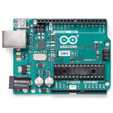
Arduino Uno (R3)
The most popular board among Arduino boards is Arduino Uno. A lot of electronic hobbyists prefer this board to its ideal size, cost, and features it supports.
The below image gives the pin configuration for this board. You can also see how different pins are connected to the internal MCU pins.

Image Source: electronicshub.org
Highlighted below are some of the important and commonly used MCU pin connections to the board. Keeping this in handy will help during your projects for making connections to external hardware.
read more : Difference Between Arduino and Raspberry Pi
External interrupt
[2] - 2, 3
[number in the bracket indicates the number of pins/modules available on the board]
Analog pins [6]: A0-A5 pins.
Digital Pins
[14]: 0-13 pins.
PWM [6]: 3,5,6,9,10,11 (490 Hz except 5 and 6 which run on 980 Hz)
Serial
[1] : 0 (RX) 1 (TX)
I2C
A4 (SDA) , A5 (SCL)
SPI
10 (SS), 11 (MOSI), 12 (MISO), 13 (SCK).
DC Current per I/O pin: 20mA
DC current for 3.3V pin: 50mA
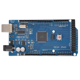
Arduino Mega (R3)
There will be times when you will run out of pins on Arduino Uno while doing large projects. Then you will have to shift to Arduino mega. It has got a bunch of peripherals and GPIO pins.
The below image gives the Pin configuration for Arduino Mega

Following is the list of frequently used connections of the MCU peripherals to the board’s pins for Mega:
read more : Arduino VS NodeMCU
External interrupt
[6] : Digital pin 2,3,18,19,20,21.( pins 20 and 21
Are not available to use for interrupts while they are used for I2C communication.)
Analog
[16] : A0-A15
Digital
[54] : 0-53
PWM
[15] : 2-13, 44-46. (490 Hz except 4 and 13 which use 980 Hz)
Serial
[4] : 0 (RX) 1 (TX); 19 (RX1) 18 (TX1); 17 (RX2) 16 (TX2)
I2C
[1]: 20 (SDA) 21 (SCL)
SPI
[1]: 50 (MISO), 51 (MOSI), 52 (SCK), 53 (SS).
DC per I/O pin 20mA
DC current for 3.3V 50mA
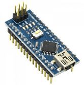
Arduino Nano
Each board has got unique qualities. As the name suggests its size is nano meaning very small and it can directly fit on a breadboard making connections very easy and fast for testing + supporting USB connections!
read more : Which Arduino Board to Buy
The below image gives the Pin configuration for Arduino Nano.

Following is the list of frequently used connections of the MCU peripherals to the board’s pins for Nano:
External interrupt
[2] : 2, 3
Analog
[8]: A0-A7.
Digital
[22]: D0-D13, A0-A7.
PWM
[6]: 3,5,6,9,10,11 (490 Hz except 5 and 6 which run on 980 Hz)
Serial
[1]: 0 (RX) and 1 (TX).
I2C
[1]: A4 (SDA), A5 (SCL).
SPI
[1]: 10(SS), 11(MOSI), 12 (MISO), 13 (SCK).
DC Current per I/O: 40mA
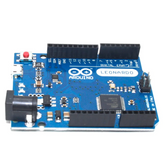
Arduino Leonardo
This board combines USB support ( which Arduino Uno and Mega don't have ) and a power jack for the power supply. ( which nano doesn't have).
The below image gives the Pin configuration for Arduino Leonardo.

Following is the list of frequently used connection of the MCU peripherals to the board’s pins for Leonardo:
External interrupt
[4] : 0, 1, 2, 3, 7
Analog
[12] : A0-15, A6-A11 (4,6,8,9,10,12)
Digital
[20] : 0-13, SCL, SDA and A0-A5.
PWM
[7] : 3,5,6,9,10,11,13. (490 Hz except 3 and 11. They use 980Hz)
Serial
[1] : 0 (RX) and 1 (TX).
I2C
[1] : SDA and SCL.
SPI
[1] :
These pins are on the ICSP header. SPI pins on this board are not connected to any of the digital I/O.
Current per IO 40mA
Current for 3.3V pin 50mA
read more : Arduino Uno Pin Diagram: A Complete Guide
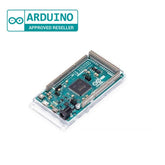
Arduino Due
The main difference between Arduino mega and Due is that Arduino due processor uses a 3.3V voltage level which reduces the power consumption of the MCU. So if you make a robot that uses too many peripherals and you want the robot’s battery to last longer then you would go for this board. Moreover, it also comes with a JTAG interface for testing.
The below image gives the Pin configuration for Arduino Due

Following is the list of frequently used connections of the MCU peripherals to the board’s pins for Due:
External interrupt
All digital pins
Analog input
[12] : A0-A11
Analog output
[2]: DAC0 and DAC1.
Digital I/O
[54] : 0-53
PWM
[12] : 2-13 (1000Hz)
Serial
[4] : 0 (RX0) 1 (TX0) 14 (TX3) 15 (RX3) 16 (TX2) 17 (RX2) 18 (TX1) 19 (RX1).
I2C/TWI
[2] : 20 (SDA) 21 (SCL), SCL1, SDA1
SPI
[2]: Has two SPI buses but the Arduino library just supports one. Refer to the image and you could see the SPI “header.”( in the image labeled as SPI for SAM3X8E).
Total allowable DC output current on all I/O lines 130mA
Current for 3.3V pin 800mA
Current for 5V pin 800mA
JTAG header:
Used for in-system debugging to test interconnections/traces between different peripherals of the PCB while the program is running on the MCU.
Instead of using the traditional probing method i.e. taking a multimeter and testing the PCB for fault, we can use JTAG to detect this. It reduces the test time of embedded products.
A BSDL(Boundary-scan description language) file is used for the application of boundary-scan testing using JTAG. It represents how the boundary scan TAP pins, TAP instructions, device pins, and boundary register pins and cells are related.
Arduino Due board runs at 3.3V compared to the other counterparts which run at 5V.
read more : Compatible Arduino Boards: Everything You Need to Know
Lilypad Arduino
LilyPad boards are made to be sewn together using conductive threads to build soft,sewable, interactive e-textile (electronic textile) projects.
LilyPad doesn't have a USB to UART converter so you will need a converter like FTDI to program LilyPad.


The below image gives the Pin configuration for Arduino LilyPad.

Following is the list of frequently used connections of the MCU peripherals to the board’s pins for Arduino LilyPad:
External interrupt
Analog
[6]: A0-A5
Digital
[14] : 0-13
PWM
[5] : 5,6,9,10 and 11.
PWM pins are not marked with a ~ sign.
Serial
[1] : 0 (RX) and 1 (TX)
I2C
[1] : A4 (SDA) and A5 (SCL)
SPI
[1] : 10 (SS), 11 (MOSI), 12 (MISO) and 13 (SCK).
DC current per IO 40mA.
You can provide a max of 5.5V to LilyPad Arduino.
read more : Interfacing ACS712 with Arduino
Arduino Micro
Compared to nano this board comes with slightly more peripherals than nano to meet your project needs.
The below image gives the Pin configuration for Arduino Micro.

Following is the list of frequently used connections of the MCU peripherals to the board’s pins for Micro:
External interrupt
[4] : 0,1,2,3,7.
Analog
[12] : A0-A5,4,6,8,9,10,12
(Note: some pins overlap with digital pin)
Digital
[20] : 0-19
PWM
[7] : 3,5,6,9,10,11 and 13.
Serial
[1] : 0 (RX) and 1 (TX)
I2C
[1] : 2 (SDA) and 3 (SCL)
SPI
[1] : MISO, MOSI, SS, and SCK.
Current per I/O pin:
20mA
Current for 3.3V: 50mA
Vin - 6-9V
Arduino Pro Mini
This board is cheaper than micro but requires an external FTDI programmer. Also, it consumes less power than micro
The below image gives the Pin configuration for the Arduino Pro mini.

Following is the list of frequently used connections of the MCU peripherals to the board’s pins for Pro Mini:
External interrupt
[2]: pin 2 and pin 3.
Analog
[6]: Pins A0 to A5.
Digital
[14] : 0-13.
PWM
[6] : Pin nos. 3,5,6,9,10 and 11.
Serial
[1] : Pin 0 (RX) and Pin 1 (TX).
I2C
[1] : Pin nos. A4 (SDA) and A5 (SCL).
SPI
[1] : Pin nos. 10(SS), 11(MOSI), 12 (MISO), 13 (SCK).
LED: Pin 13
DC current per IO : 40 mA
read more : IR Sensor Interfacing with Arduino
Conclusion
In this blog post, we have learned that understanding the pin configurations of various Arduino boards can greatly enhance your ability to create innovative and unique projects. Whether you're using the versatile ARDUINO UNO (R3), the powerful ARDUINO MEGA (R3), or any of the other boards such as ARDUINO NANO, ARDUINO LEONARDO, ARDUINO DUE, LILYPAD ARDUINO, ARDUINO MICRO and ARDUINO PRO MINI, knowing how to properly connect your sensors and components can make all the difference. So dive in and start exploring the endless possibilities of Arduino today! And remember, with the right knowledge and creativity, you can bring any idea to life.
If you appreciate our work don't forget to share this post and leave your opinion in the comment box.
Please do check out other blog posts about Interfacing ACS712 with Arduino , Arduino Interfacing with Ultrasonic Sensor , LED Interfacing with Arduino , Interfacing GSM Module with Arduino , Interfacing MAX30100 Pulse Oximeter with Arduino , IR Sensor Interfacing with Arduino , How to connect ZMPT101B to Arduino and How to use Buzzer with Arduino.
Make sure you check out our wide range of products and collections (we offer some exciting deals!)
Excerpt
Frequently Asked Questions
1. What are the RX and TX pins of Arduino?
The RX and TX pins on an Arduino board facilitate the exchange of information between the device and external entities through a serial protocol. The RX pin, designated for reception, receives data sent from an external entity to the Arduino. Conversely, the TX pin, meant for transmission, transmits data from the Arduino to the external entity. These pins often connect with sensors or computers, using a serial protocol like UART or USART.
2. How to set a pin in Arduino?
If you gotta choose a pin for your Arduino project, there's a whole bunch of them. Once you've finally picked one, you gotta set its mode as either input or output using this function called pinMode(). If you want it to be output, you can use digitalWrite() to set it to either HIGH or LOW. And if you wanna read an input pin, you can use digitalRead() to get its state.
3. Is Arduino input or output?
Arduino, a microcontroller platform, performs both input and output tasks through its versatile pins, which read data from sensors and control actuators like LEDs and motors. Additional modules such as shields expand its capabilities. Arduino's popularity in electronics, robotics, and automation projects stems from its flexibility, which enables a wide range of functions.
4. What are the different types of pins on an Arduino board?
Arduino boards feature various pins: digital pins for binary input/output, analog pins for reading varying voltage levels, power pins for supplying voltage, PWM pins for pulse-width modulation, and ground pins for circuit connection. Each type serves specific functions, making Arduino boards versatile for numerous electronics projects.
5. How many digital and analog pins does an Arduino Uno have?
The Arduino Uno has 14 digital pins, numbered from 0 to 13, and 6 analog pins, labeled A0 to A5. These pins allow for various input and output operations, making the Uno ideal for both simple and complex projects.
6. What are power pins on Arduino and what do they do?
Power pins on an Arduino board include 5V, 3.3V, and GND. The 5V pin supplies voltage for most components, while the 3.3V pin is used for low-power devices. The GND pin serves as a common ground reference for your circuit, ensuring proper operation.
7. What is PWM and which pins on Arduino support it?
PWM, or Pulse Width Modulation, allows for variable power delivery to devices like motors and LED brightness. On the Arduino Uno, PWM is supported on digital pins 3, 5, 6, 9, 10, and 11. These pins produce a PWM signal when programmed correctly.
8. How do you identify ground and Vcc pins on the Arduino board?
Ground pins are typically marked as "GND" and usually located near the power section of the board. The Vcc pins supply voltage and are labeled as "5V" or "3.3V." These labels help ensure you connect components correctly to avoid damaging your circuit.
9. What is the function of the AREF pin on Arduino?
The AREF pin, or Analog Reference pin, is used to set the upper limit for analog input readings. By providing an external reference voltage, you can improve the accuracy of your analog measurements when using the Arduino's analog pins.
10. How can you use the ICSP header on Arduino?
The ICSP (In-Circuit Serial Programming) header on Arduino allows you to program the microcontroller directly using a programmer. This is useful for advanced users who want to upload custom code without using a bootloader. It provides a direct connection to the microcontroller’s flash memory.
11. Can you use multiple boards and share pins?
Using multiple Arduino boards in a single project is feasible, but sharing pins can lead to conflicts. Each board should have its own unique pin assignments to avoid confusion. Consider using multiplexers or I2C communication for better management when integrating several boards.
12. What should you avoid when wiring pins incorrectly?
When wiring pins incorrectly, avoid connecting power pins directly to ground or mixing up input and output pins. Such mistakes can cause short circuits, potentially damaging the board or connected components. Always double-check connections before powering on.
13. How do you know which pin to use for I2C or SPI on Arduino?
For I2C communication, use the dedicated SDA (data line) and SCL (clock line) pins, which differ by Arduino model—often A4 and A5 on the Uno. For SPI, use MOSI, MISO, SCK, and SS pins, typically 11, 12, 13, and 10 on the Uno. Always consult your board's documentation for clarity.


