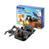
QD022 ACEBOTT ESP32 Robot Arm Kit Assembly Guide
Summary
So, you’ve taken the exciting step of purchasing the QD022 ACEBOTT ESP32 Robot Arm Kit.
After unboxing it, you're looking at a promising collection of motors, brackets, and electronics.
While the initial view of loose components can seem a bit intimidating, don’t worry!
This comprehensive guide is designed to transform that box of parts into a fully assembled, functional robotic arm.
We will walk you through every step with clear instructions and helpful tips, ensuring a smooth and rewarding building experience.
By the end, you'll be ready to bring your creations to life. Let's get started.

What is the QD022 ACEBOTT ESP32 Robot Arm Kit
The QD022 ACEBOTT ESP32 Robot Arm Kit is a 4-DOF (Degrees of Freedom) programmable robot arm designed specifically for beginners to learn robotics and programming.
This educational kit uses an ESP32 controller board and allows users to understand how robot arms function through hands-on assembly and programming.
The kit is designed for STEM education and teaches essential skills, including ESP32 programming using Arduino IDE, C/C++ programming basics, servo motor principles, and robotics concepts.
It's suitable for students aged 12 and above, making it ideal for classrooms, workshops, and hobbyist projects
Step-by-Step Assembly Guide
Here is a comprehensive step-by-step guide to assemble your Robot Arm Kit.
Phase 1: Preparation, Parts Check, and Controller Board Installation
Step 1: Unpack and Verify Components

- Take all parts out of the package
- Check all electronic components against the included parts list
Step 2: Prepare Acrylic Components

- Remove all protective paper attached to the acrylic panels
- Install the Controller Board
- Install the base plate
Phase 2: Joystick Module Setup

Step 3: Install Joystick Modules
- Critical: Ensure joystick modules are connected with proper wires
- Pass the wires through the designated wire routing holes in the frame
Step 4: Connect Left Joystick Module
Connect the left joystick module wires to the ESP32 controller as follows:
- SW → Pin 34
- X → Pin 32
- Y → Pin 33
- VCC → VCC
- GND → GND
Step 5: Connect the Right Joystick Module
Connect the right joystick module wires to the ESP32 controller as follows:
- SW → Pin 39
- X → Pin 35
- Y → Pin 36
- VCC → VCC
- GND → GND
Phase 3: Servo Motor Preparation and Calibration

Step 6: Servo Shaft Orientation Setup
- Position all servo shafts according to the specified orientation
- This step is crucial for proper arm movement
Step 7: Install Servo Wheels (Critical Step)
- Important: Install the steering wheel with the protrusion facing the circular hole
- Do NOT put the steering wheel in the wrong direction - this will cause a malfunction
- Repeat this for all servo motors that require steering wheels
Step 8: Base Servo Calibration
- Insert two 18650 batteries to supply power to the controller board
- Connect the base servo to GPIO Pin 5 of the controller board
- Turn on the power switch
- The servo angle will automatically adjust to the correct position
- Once calibrated, unplug the wire and turn off the power
Phase 4: Chassis and Base Assembly

Step 9: Install Base Structure
- Install the base components in the correct orientation
Step 10: Attach Base Bracket
- Important: The bracket should be attached to the outer side of the disc bracket
- Warning: Do not tighten screws too tightly - ensure joints can move properly
Phase 5: Shoulder and Elbow Assembly

Step 11: Install Elbow Bracket
- Critical: The two rectangular holes of the elbow bracket must be positioned above
- Use the appropriate short and long columns as specified
Step 12: Servo Shaft Positioning
- Important: The servo shaft should face outward
- Double-check this orientation before proceeding
Step 13: Shoulder and Elbow Servo Calibration
Perform the following calibration sequence:
- Connect the shoulder servo to GPIO Pin 16 of the controller board
- Connect the elbow servo to GPIO Pin 17 of the controller board
- Turn on the power switch
- The servo angles will automatically adjust
- Unplug wires and turn off power once calibration is complete
Step 14: Install Shoulder Bracket
- Critical: The shoulder bracket should be installed vertically to the ground
- Only tighten the screws of the servo motor and nylon column after ensuring proper vertical alignment
Phase 6: Wrist Assembly

Step 15: Wrist Servo Installation
- Important: Ensure the steering shaft and circular hole are both positioned upwards
- Do not fully tighten the mounting screw yet - leave it loose for now
Step 16: Wrist Servo Calibration
- Connect the wrist servo to GPIO Pin 18 of the controller board
- Turn on the power switch
- The servo angle will automatically adjust
- Unplug the wire and turn off the power
- Warning: Do not tighten too tightly - ensure joints can move properly
Phase 7: Claw Assembly

Step 17: Install Claw Mechanism
- Important: The initial form of the claw should be in the closed position
- Ensure the rectangular hole is facing upwards
Step 18: Final Bracket Alignment
- Critical: Ensure the elbow bracket and shoulder bracket are installed at a 90-degree angle
- This is essential for proper arm kinematics
Phase 8: Final Wiring and Testing

Step 19: Route Servo Wires
- Important: Thread the servo wires through the designated hole from top to bottom
- Ensure all cables are properly routed and not pinched
Step 20: Final Wiring Connections
Critical Step: Ensure all cables are correctly connected before powering on to avoid burning modules and the controller board.
Final servo connections (from bottom to top):
- Base servo → GPIO Pin 5
- Shoulder servo → GPIO Pin 16
- Elbow servo → GPIO Pin 17
- Wrist servo → GPIO Pin 18
Step 21: Final System Test
- Insert two 18650 batteries
- Turn on the power switch
- Test all joints for proper movement
- Verify joystick control functionality
- Check that all servos respond correctly
Critical Safety Notes
- Always ensure proper servo shaft orientation before installation
- Never overtighten screws - joints must move freely
- Double-check all wiring connections before powering on
- Install brackets at correct angles (90 degrees between elbow and shoulder)
- Verify servo calibration at each step before proceeding
Conclusion
Congratulations on successfully assembling your QD022 ACEBOTT ESP32 Robot Arm! By meticulously following each phase, you have transformed a collection of components into a fully operational robotic tool.
You’ve calibrated the servos, wired the joystick controls, and pieced together the mechanical structure.
Now, it's time to power up your new robotic arm, explore its range of motion, and start programming it to perform tasks.
Enjoy the satisfaction of building your own robot and discovering its full potential.


