✨ Use RCAPP
and get 5% off 👇


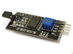
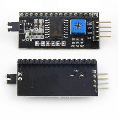
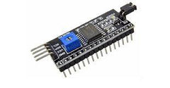
16x2 LCD I2C Interface Adapter
Let us know!
We'll try to match the price for you

Couldn't load pickup availability


Are you looking to buy a reliable 16x2 LCD I2C Interface Adapter in India at an unbeatable price? Robocraze has the perfect solution for you. This 5V I2C module is the go-to choice for various applications, and it's currently available at a good discount. Don't miss out on this amazing offer.
This IIC/I2C serial interface adapter module, commonly used as an I2C LCD module, provides hassle-free serial I2C control, making it a breeze to integrate with your Arduino projects and other microcontroller-based systems. Whether you're a hobbyist or a professional, this I2C LCD solution simplifies your work and helps you achieve your project goals.
This I2C module is compatible with both 16x2 and 20x4 Character LCD Display Modules, supporting 4-bit mode. The default I2C address is 0x3F, but you can modify it as needed. With two IIC interfaces, you can quickly connect this adapter using Dupont lines or dedicated cables.
This 16x2 LCD I2C Interface Adapter is not just about convenience; it's also about quality. It's RoHS-compliant, guaranteeing durability and reliable performance for your projects. So, whether you're working on robotics, automation, or DIY builds, this I2C LCD module simplifies the process and saves you valuable time.
Ready to take control of multiple displays with ease? Buy this efficient I2C module for LCD from Robocraze now and get your projects up and running without a hitch.

| IC Chip | PCF8574 |
| Input Voltage Range(VDC) | 5 |
| PCB Size ( L x W ) mm | 42 x 20 |
| Weight (gm) | 4 |
I2C is a single-ended, synchronous, multi-slave, multi-master packet switched serial bus. In other words, multiple chips can be connected to the same bus. I2C employs only two bidirectional open collector or open drain lines, Serial Data Line (SDA) and Serial Clock Line (SCL), which are connected with resistors.
The I2C Bus allows two devices to communicate with each other in a stable, high-speed, bidirectional manner while using the fewest I/O pins. Because the I2C Bus communicates over two lines, Serial Data Line (SDA) and Serial Clock Line (SCL), the protocol used by I2C is also known as a "bidirectional" protocol.
Simply connect the I2C module to the LCD in parallel and the I2C module's four pins to the Arduino. The I2C module has four output pins: VCC, GND, SDA, and SCL, and it receives 5V from the Arduino via VCC and GND. SDA is the data pin and SCL is the clock pin of the I2C module.
The I2C protocol for LCDs uses two wires such as SDA for data and SCL for the clock. It begins with a start condition, followed by addressing, and data transmission, and ends with a stop condition. The LCD controller determines specific commands and data formats.
The I2C communication protocol of the adapter allows control of up to three LCD displays on a single I2C bus, simplifying multi-display projects.


