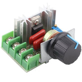
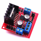
What is Motor Driver
Summary
Are you curious about how motors are controlled in devices like robots, drones, and CNC machines? If the answer is yes! then check out this blog post which gives you an overview of motor drivers, including the different types available and how they work. You will also learn about the H-bridge circuit, how to build a motor driver circuit and the direction-controlling circuit of a DC motor using transistors. If you're interested in learning more about motor control, then this blog post is a must-read!
Introduction
Motor drivers are a vital part of any robotics or automation project. They provide the power needed to control motors and other components within an application. The motor driver is essentially responsible for providing the voltage, current, directionality and protection necessary to efficiently operate your robotic parts or devices. By connecting directly with one's microcontroller board easy interfacing can be established allowing you to customize settings such as acceleration/deceleration rates, Encoder measurements and PID tuning parameters in order for improved system performance unrestricted by its hardware limitations; this will have large implications when it comes time troubleshoot issues pertaining those aspects of operation during deployment phases. Motor Drivers play an essential role throughout much industrial production where precision accuracy concerning motion systems must remain top priority accompanied alongside data collection capabilities that allow constant monitoring on how well ones setup is performing at all times.
The most commonly used actuator in any electronic device/machine will be motors next to solenoids, pneumatics, and hydraulics. These DC machines can be found everywhere, from a simple vibration motor inside a phone to complex stepper motors in CNC machines. A Motor Driver or Motor Controller is required to control a motor using a Microcontroller or processor. Motor Drivers come in a variety of shapes and sizes, depending on the type of motor and control required. In this article, we will focus only on DC motors and how to control a DC motor using a Motor Driver with the most popular H-bridge Topology. This technique will help us drive small or large DC Motors and also control its direction.
What is a motor driver?
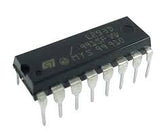
A motor driver IC is an integrated circuit chip that controls motors in autonomous robots and embedded circuits. L293D and ULN2003 are the most commonly used motor Driver IC that is used in simple robots and RC cars. A motor driver is unquestionably something that causes the motor to move in accordance with the given instructions or inputs (high and low). It listens to the low voltage from the controller/processor and controls an actual motor that needs high input voltage A motor driver IC, in simple terms, controls the direction of the motor based on the commands or instructions received from the controller. Many motor drivers follow different topologies, in this article, we will focus on the popular H-bridge topology which is used in the L293D motor driver IC

A motor is an electronic device that helps convert electrical energy into mechanical energy. Therefore, a motor driver enables you to perform automatic tasks using electrical power. We have several types of electric motors. These types include the DC motors, the stepper motors, and the Servo motors. These motors are distinguished by their operating principles and characteristics. Choosing the correct type of motor driver is essential because it allows your engine to work efficiently with the microcontroller of your choice. This article will help you understand how the motor driver works, the characteristics, types, etc., Let's begin!
Different Types of Motor drivers
| Motor driver | Description | Image |
| 1. L293D IC |
|
 |
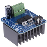
| 2. BTS7960B motor driver board |
|
 |
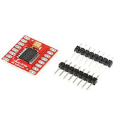
| 3. TB6612FNG motor driver board |
|
 |
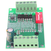
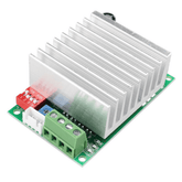
| 4. TB6560 motor driver board |
|
 |
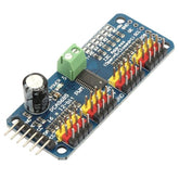
| 5. PCA9685 16 channel Servo motor driver board |
|
 |
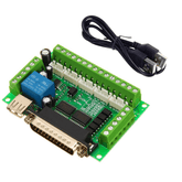
| 6. MACH3 Interface Board CNC 5 Axis |
|
 |
| 7. TB6600 Stepper motor driver |
|
 |
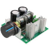
| 8. PWM DC motor speed controller |
|
 |
| 9. 2000W 220V AC motor speed control board |
|
 |
| 10. L298 Motor driver board |
|
 |
| 11. A4988 Stepper motor driver |
|
 |
How does a motor driver work?

First, the microcontroller sends signals to the motor drive. Then, the signals received by the motor driver are interpreted and stepped up with the reference voltage i.e provided for driving the motor. The motor has two voltage input pins. Pin 1 turns ON the motor by giving the voltage equal to the reference voltage, whereas pin 2 turns OFF the motor by giving 0V at the output pin. This entire process is controlled by the motor driver. We use motor drivers to give high power to the motor by using a small voltage signal from a microcontroller or a control system.
If the microprocessor transmits a HIGH input to the motor driver, The driver will rotate the motor in one direction keeping the one pin as HIGH and one pin as LOW. And when the microcontroller transmits a LOW input to the motor driver, the motor driver makes the motor to rotate in other direction by making 2 motor pins as LOW and HIGH alternatively.
Motor drivers are important components in machines and robotic systems. They enable the operation of motors from a higher level signal, such as pulse-width modulation (PWM) or analog signals like those used with servos. Motor driver circuitry typically includes an integrated circuit that can supply enough current to drive the motor, while also providing shaft control for precise speed adjustment through power transistors connected in parallel with each other.
By configuring these transistors correctly, voltage spikes resulting from rapid switching of motor coils on tight turns can be controlled effectively without compromising efficiency during normal operations. Furthermore, many modern designs offer features such as built-in sensors which detect stall conditions as well as over/undervoltage protection and active braking capability making them ideal solutions for many applications ranging from light automation to complex robotics projects alike.
Also, read our blog on the Working Principle of AC Motor explaining how AC motor works with diagram and different types of AC motors and how they work.
What is a H-Bridge circuit?
This section explains what an H-bridge is, how it is made, and the common parts. The video also discusses how to drive a brushed-DC motor with an H-Bridge, Coast, and Brake.
An H-bridge is a simple circuit that allows you to control the direction of a DC motor. It is typically used in conjunction with a microcontroller, such as an Arduino, to control motors. You can build a robot if you can control two motors to move forward or backward.


If you instead close switches 2 and 3, you will have plus connected to the right and minus connected to the left, and the motor spins in the opposite direction.
How to build a motor driver circuit?
Direction controlling circuit of a DC motor using Transistors

The resistors going into each base is there to reduce the current to each transistor. Not sure how to calculate it? If you’re using a microcontroller to control them, start with 1k and adjust if that doesn’t work.
This entire circuit requires a voltage source and PWM signal for each transistors to control the motor in terms of speed and direction. Always 2 transistor in opposite direction will be fed with a PWM signal to control the speed and direction of the DC motor.
Major components in motor drivers

1. Controller
The controller can be a microprocessor or a microcontroller.
2. Motor Driver IC or Motor Driver Circuits
They are current amplifiers that accept a low current signal from the controller and convert it into a high current signal that is used to drive the motor.
3. Motor
Motor is defined as an electric or mechanical device that can create a motion. While interfacing with the controller; some of the motors like DC motor, stepper motor, and brushless dc motor may require a driver IC or driver circuit. DC motor is a type of motor that can convert DC into a mechanical power. In a brushless DC motor, it consists of a DC power source, and an inverter producing an AC signal to drive the motor. While stepper motor is a brushless DC electric motor that converts electrical pulses into discrete mechanical motions.
4. Power Supply Unit
Provides the required power to the motor drive.
Conclusion
In this blog, we have learned about the basics of motor drivers and how to use them. This blog covers the basic concepts of motor drives circuits and their uses. We hope this tutorial blog helped you in getting started with the motor driver circuits.
If you appreciate our work don't forget to share this post and leave your opinion in the comment box.
Please do check out other blog posts about Popular electronics
Make sure you check out our wide range of products and collections (we offer some exciting deals!)
Excerpt
Frequently Asked Questions
1. What does a motor driver do?
A motor is an electronic device that assists in the conversion of electrical energy to mechanical energy. As a result, a motor driver enables you to perform automatic tasks using electrical power.
2. Is motor driver necessary?
So, in general, any motor requires a driver circuit because its voltage/current requirements differ from the device that's trying to control it.
3. What is a motor driver unit?
Motor Driver circuits are current amplifiers. They act as a bridge between the controller and the motor in a motor drive. Motor drivers are made up of discrete components that are integrated inside an integrated circuit (IC).
4. What is the difference between motor driver and motor controller?
The main difference between a motor controller and a motor driver is that the controller is responsible for controlling the speed, torque, the direction of the motor whereas a motor driver is responsible for providing enough electrical power to the motor as required.
5. What is a motor driver and why do we need one?
A motor driver is an electronic circuit that controls a motor's speed and direction by taking commands from a microcontroller. It amplifies the control signals, allowing the motor to operate at higher power levels. Motor drivers are crucial for robotics and automation, enabling precise control and efficient energy usage.
6. How does a motor driver work to control speed and direction of a motor?
A motor driver uses pulse-width modulation (PWM) to regulate the voltage supplied to the motor, effectively controlling its speed. To change direction, it switches the polarity of the voltage. This combination allows for smooth acceleration, deceleration, and directional changes in various motors.
7. What is the difference between a motor driver and a motor controller?
A motor driver is a hardware component that provides power to the motor while interpreting control signals. In contrast, a motor controller is often a software-based system or device that generates those control signals. Essentially, the motor driver executes the commands given by the motor controller.
8. What types of motors can be controlled by a motor driver (DC, stepper, servo)?
Motor drivers can control various types of motors, including DC motors, stepper motors, and servo motors. Each type requires specific driver configurations to accommodate their unique operating characteristics, making them versatile in robotics and automation applications.
9. What is an H-Bridge and how is it used in motor drivers?
An H-Bridge is a circuit configuration that allows a motor to be driven in both directions by controlling the polarity of the voltage supplied to it. Used in motor drivers, H-Bridges enable simple control of motor rotation and are essential for applications requiring bidirectional movement.
10. How do you choose the right motor driver IC for your project?
To select the right motor driver IC, consider factors like voltage and current ratings, compatibility with your motors, and the required features (like PWM control). Assess your project's specific needs, including motor type and performance requirements, to make an informed choice.
11. Can a microcontroller directly drive a motor without a driver?
A microcontroller can technically drive a small motor directly, but this approach is not recommended. It may damage the microcontroller due to high current or voltage requirements. Using a motor driver ensures safe operation and better control over speed and direction.
12. What are common motor driver ICs for hobby electronics (e.g., for Arduino)?
Common motor driver ICs for hobby electronics include the L298N and L293D for DC and stepper motors. For Arduino projects, the A4988 and DRV8825 are popular choices for stepper motors due to their ease of use and integrated features. These ICs facilitate seamless motor control.
13. What protection features should you look for in motor drivers (over-current, thermal)?
Look for protection features such as over-current protection, thermal shutdown, and under-voltage lockout in motor drivers. These features safeguard both the driver and the motor from damage, enhancing reliability and longevity in various applications.
14. What are the limitations of using motor drivers in robotics or automation?
Motor drivers can have limitations like heat dissipation issues, maximum voltage, and current ratings. They may also lack advanced features like feedback control, which can limit precision. Understanding these constraints helps in selecting the appropriate drivers for specific robotics or automation tasks.


