Simple Steps to Interfacing 16x2 LCD with Arduino
Summary
When you build projects with Arduino, you create a connection between the physical and digital worlds. While your Arduino can sense its environment, it needs a way to talk back to you.
A 16x2 Liquid Crystal Display (LCD) is a fantastic and low-cost way to give your project a voice, displaying everything from sensor data and status messages to custom menus.
This guide will walk you through the simple steps to connect and program an LCD, opening up a new dimension of interactivity for your creations.

How a Liquid Crystal Display (LCD) works
To understand how an LCD module works, imagine a room with a brightly lit wall and a window covered by a set of tiny, electronically controlled Venetian blinds.
Each blind slat can be twisted open or shut. By selectively opening and closing certain slats, you could block the light in specific patterns to form letters or numbers. A Liquid Crystal Display operates on a very similar principle, but on a microscopic scale.
The "liquid crystal" part refers to a special substance that is in a state between a liquid and a solid. Its molecules have the interesting property of twisting when an electric voltage is applied.
The display is made of a grid of tiny segments called pixels. Each pixel is like one of those tiny Venetian blinds. It sits in front of a backlight, which is the "brightly lit wall."
When no voltage is applied to a pixel, the liquid crystals within it are in a twisted state that allows light from the backlight to pass through to a polarizing filter, and the pixel appears bright. When voltage is applied, the crystals untwist. This new alignment blocks the light, and the pixel appears dark.
On a character LCD like the 16x2 model, the onboard controller chip takes the characters you send it and calculates which pixels in its 16-column, 2-row grid need to be turned on or off to display that character. It's a clever system of controlled light-blocking that lets us display useful information.
16x2 LCD Display Module Pinout
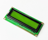
Before you can make the connections, you need to understand the function of each pin on the LCD module. As shown in the image , a standard 16x2 LCD has a 16-pin interface. Here is a breakdown of what each pin does, based on the labels shown on the circuit board:

- Pin 1 (VSS): Labeled as Ground, this is the main ground connection for the module.
- Pin 2 (VCC): This is the power supply pin, labeled as +5V, which powers the logic circuitry of the display.
- Pin 3 (VEE): This pin is for Contrast control. By adjusting the voltage on this pin, you can change the sharpness and visibility of the characters on the screen.
- Pin 4 (RS): The Register Select pin. This pin is used to switch between command mode (to send instructions like "clear screen") and data mode (to send characters to be displayed).
- Pin 5 (R/W): This is the Read/Write pin. It sets the module to either read mode or write mode. For most projects, this is connected to Ground to keep it permanently in write mode.
- Pin 6 (E): The Enable pin. A high-to-low pulse on this pin tells the LCD to latch the data present on the data pins.
- Pins 7-14 (D0-D7): These are the eight Data Pins (Data Pin 0 to Data Pin 7). They carry the 8-bit data that you send to the display. To save pins on the Arduino, projects often use a 4-bit mode which only requires pins D4 through D7.
- Pin 15 (LED+): This pin powers the screen's backlight. It's labeled as LED+ 5V, indicating it should be connected to a 5V source.
- Pin 16 (LED-): This is the backlight's ground connection, labeled LED- Ground.
Steps to Interfacing 16x2 LCD with Arduino
Now that you understand the pins, let's get everything connected. This section provides all the details you need to interface a 16 x2 LCD display with an Arduino board. We will use the common 4-bit mode to conserve digital pins on the Arduino.
Components needed
Before starting, gather all the necessary parts. Having everything on hand makes the process much smoother.
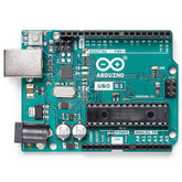
- Arduino UNO or a similar compatible board
- 16x2 Character LCD Module (with pin headers soldered)
- Solderless Breadboard
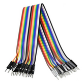
- A set of male-to-male jumper wires
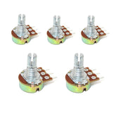
- 10k Potentiometer
- 220 Ohm Resistor (optional, for backlight protection)
Circuit Diagram
The circuit is the blueprint for our project. The LCD module to Arduino connection diagram shows how each component is wired together.

Assembly Instructions
Follow the connections shown in the circuit diagram to wire your 16×2 LCD to an Arduino. This process of Interfacing 16x2 LCD with Arduino is a foundational skill in electronics, and the provided diagram makes it straightforward.
1. Power and Ground Rails:
- Connect the Arduino's 5V pin to the red wire, which leads to the LCD's VCC (Pin 2) and the LED+ (Pin 15).
- Connect the Arduino's GND pin to the black wire, which leads to the LCD's VSS (Pin 1), RW (Pin 5), and the LED- (Pin 16). This common ground is essential for the circuit to function.
2. Contrast Potentiometer:
The diagram shows a potentiometer (the component with a resistor symbol and an arrow) used for contrast.
- One outer leg of the potentiometer connects to the 5V line (red wire).
- The other outer leg connects to the GND line (black wire).
- The center pin of the potentiometer is connected via the yellow wire to the LCD's VEE (Pin) This allows you to adjust the screen's contrast.
3. Control and Data Connections:
The diagram details how to connect the LCD module to Arduino for 4-bit communication.
- Connect the LCD's RS (Pin 4) to Arduino's Digital Pin 12 (light green wire).
- Connect the LCD's E (Pin 6) to Arduino's Digital Pin 11 (dark green wire).
- Connect the LCD's data pins D4 (Pin 11), D5 (Pin 12), D6 (Pin 13), and D7 (Pin 14) to the Arduino's Digital Pins 5, 4, 3, and 2 respectively, as shown by the blue wires.
By following this wiring scheme, you will correctly interface to the LCD screen, preparing it for the code that will bring it to life.
Arduino Code
With the hardware assembled, the final step is to upload the code. The Arduino IDE includes a built-in library, LiquidCrystal.h, which makes communicating with the LCD incredibly simple.
The following Arduino Code to Interface 16x2 LCD will initialize the display and print a welcome message.
This simple Arduino 16x2 LCD code also serves as a way to Test the 16X2 LCD Module and your wiring. If the message appears, you know everything is working correctly.
// Include the LiquidCrystal library
#include

// Initialize the library with the numbers of the interface pins
// LiquidCrystal(rs, enable, d4, d5, d6, d7)
LiquidCrystal lcd(12, 11, 5, 4, 3, 2);

void setup() {
  // Set up the LCD's number of columns and rows:
  lcd.begin(16, 2);

  // Print a message to the LCD.
  lcd.print("Hello world!");
}

void loop() {
  // Set the cursor to column 0, line 1
  // (note: line 1 is the second row, since counting begins with 0):
  lcd.setCursor(0, 1);

  // Print a message to the second line
  lcd.print("LCD Tutorial");
}
After uploading this sketch, you should see the message "Hello world!" on the top line of your LCD and "LCD Tutorial" on the bottom line. If you see only black boxes or a blank screen, slowly turn the potentiometer until the text becomes clear and sharp.
Conclusion
You have now successfully interfaced a 16x2 LCD with your Arduino. This simple but powerful addition allows your projects to provide direct, readable feedback to the user, making them more interactive and user-friendly.
From here, the possibilities are vast. You can display data from sensors, create custom characters, or build menus for controlling your devices.
Mastering the LCD is a significant step, and there are many exciting Projects Using 16x2 LCD Display Module waiting for you to build, from weather stations to custom game consoles.


