AN INTRODUCTION TO ARDUINO
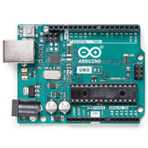
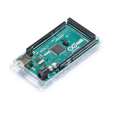
An Arduino is a single-board microcontroller designed to make the process of using electronics for multidisciplinary projects more accessible. It can sense the environment by receiving input from a variety of sensors and affect its surroundings by controlling lights, motors, and other actuators.
Arduino board designs use a variety of microprocessors and controllers. The boards are equipped with sets of digital and analog input/output (I/O) pins that may be interfaced with various expansion boards (shields) and other circuits. The boards feature serial communications interfaces, including Universal Serial Bus (USB) on some models, which are also used for loading programs from personal computers. The microcontrollers are typically programmed using a dialect of features from the programming languages C and C++.
At its core, it consists of an AtMega328P microcontroller.
Advantages:
- Open Source
- Simplified & user-friendly programming language
- No additional programmer/burner hardware required for a programming board
- Portable
- Low power consumption
Read our blog Smart Dustbin Arduino detailing Arduino code for making a smart dustbin, the required components, and the circuit diagram for making an automatic dustbin project.
INSTALLATION OF ARDUINO IDE:
- Download the Arduino IDE from the following link - Arduino Software
- Install the Arduino IDE
- When prompted to install drivers, say yes to all the drivers.
- Next, you need to find the COM port of your Arduino:-
- Open Device Manager
- Click on Ports
- Note down the Arduino’s COM port number
- Open the Arduino IDE
- Select your board from the list and the correct serial COM Port.
- Upload your program to the Arduino board.
Read our blog IR sensor Arduino code for Interfacing IR Sensor Module with Arduino where we explain Arduino Code and steps in uploading the code to the Arduino board.
BLINK LED
The first program every programmer learns consists of writing enough code to make their code show the sentence "Hello World!" on a screen. The blinking LED is the "Hello World!" of physical computing.
An LED is a small light (it stands for "light emitting diode") that works with relatively little power. The Arduino board has one built-in digital pin 13. In this experiment, we will blink the internal LED at digital pin 13.
Note: If you are using an external LED, connect the LED with care. LEDs have polarity, which means they will only light up if you orient the legs properly. The long leg is typically positive and should connect to a digital pin on the Arduino board. The short leg goes to GND; the bulb of the LED will also typically have a flat edge on this side. In order to protect the LED, you will also need to use a resistor "in series" with the LED.
read our blog explaining the difference between arduino and nodemcu
Program:
void setup()
{
pinMode (13, OUTPUT);
}
void loop()
{
digitalWrite (13, HIGH);
delay (1000);
digitalWrite (13, LOW);
delay (1000);
}
Every Arduino Sketch (program) must compulsorily have two main functions – Setup and Loop. The Setup function runs once whenever the Arduino is powered on or reset. The Loop function repeats itself continuously until the Arduino is powered off.
The pinMode (PINNUMBER, DATADIRECTION) function is used to configure any pin on the Arduino as either an input pin or an output pin. It takes two parameters, the first one being the pin number, and the second being the required state (INPUT/OUTPUT) of the pin. For this experiment, we are selecting pin number 13 because the onboard LED on the Arduino is connected to this pin and we have connected the external LED on the Arduino board to this pin. Since the LED is an actuator or an output device, we will configure pin number 13 as an output pin.
Once a pin has been configured as an output pin, we can make it either HIGH or LOW, using the digitalWrite (PINNUMBER, PINSTATE) function which again takes two parameters, the first one being the pin number, and the second one being the state of the pin. HIGH states mean this pin will output a voltage of 5V on that particular pin and LOW will make this pin 0V.
The delay (DELAYTIME) function pauses the Arduino sketch for an interval given in milliseconds.
Also, read our blog on the Ultrasonic Sensor Interfacing with Arduino detailing the connection diagram to interfacing the Ultrasonic sensor with Arduino, code, and steps.
Buy your and accessories Arduino here


