How to Connect HX711 Load Cell module to Arduino
Summary
When I first encountered this module, I was genuinely impressed by how it transforms complex load cell interfacing into a straightforward process that even beginners can master.
After working with various weighing systems and Arduino projects, I can confidently say that the HX711 Load Cell Amplifier module stands out as one of the most reliable and user-friendly solutions for precise weight measurement
In this blog post, we'll explore every aspect of connecting the HX711 to your Arduino board, from understanding the fundamental concepts to building a fully functional digital weighing system.
Whether you're a student diving into sensor technology, a maker working on IoT projects, or simply curious about how digital scales work, this guide will take you through the entire journey from basic connections to advanced calibration techniques.

What is a Load Cell and How Does It Work?
A load cell is essentially a sophisticated sensor that converts mechanical force or weight into electrical signals.
Think of it as a translator that speaks the language between the physical world of weight and the digital realm of microcontrollers.
The principle on which the load cell works is called the Wheatstone bridge configuration. Inside every load cell, there are four strain gauges arranged in a specific pattern that creates this bridge.
When you apply weight to the load cell, it causes microscopic deformation in the metal structure. This deformation changes the electrical resistance of the strain gauges, creating a small voltage difference that's proportional to the applied weight.
The challenge, however, is that these voltage changes are incredibly small—typically measured in millivolts—which is where our HX711 module becomes essential.
What makes load cells particularly impressive is their precision and reliability. The Measuring weight using Arduino projects I've worked with consistently demonstrate accuracy levels that rival commercial digital scales, especially when proper calibration is performed.
Load cells come in various configurations and weight capacities, from small 1kg units perfect for kitchen scales to massive 200kg industrial sensors capable of monitoring heavy machinery.
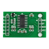
What is HX711 Load Cell Amplifier Module?
The moment I first examined the HX711 Load cell module, it became clear why this particular component has become the go-to solution for Arduino weight measurement projects.
A load cell amplifier helps amplify the signals generated by the Load cell, so that the microntrollers can easily read those signals.
As I mentioned in the previous section, A physical sensor that converts mechanical force (weight/pressure) into electrical signals. But the output signal is too weak and noisy to be directly read by microcontrollers.
This is where a load cell helps out by doing the following:
- Amplifies the tiny voltage changes from the load cell
- Converts analog signals to precise digital data
- Filters out electrical noise
- Provides a clean digital interface for microcontrollers
So, essentially, the load cell amplifier acts as a bridge between the load cell and the microcontroller.
The HX711 module features a sophisticated 24-bit ADC (analog-to-digital converter) that transforms those tiny millivolt signals from load cells into precise digital values that Arduino can easily interpret.
The module includes an integrated low-noise programmable gain amplifier with selectable gains of 32, 64, and 128, ensuring optimal signal amplification regardless of your specific load cell characteristics.
What impressed me most during testing was its dual-channel capability, allowing connection of two different load cells simultaneously for more complex weighing applications.
The HX711 breakout board operates within a wide voltage range of 2.6V to 5.5V, making it compatible with both 3.3V and 5V Arduino systems. Its power consumption remains remarkably low at less than 1.5mA during normal operation, dropping to under 1µA in power-down mode.
The module offers selectable output data rates of either 10 samples per second (SPS) or 80 SPS, with built-in 50Hz and 60Hz noise rejection to maintain stable readings even in electrically noisy environments.
The simple two-wire interface using just Clock and Data lines makes integration with any microcontroller's GPIO pins incredibly straightforward, which is why countless DIY projects for beginners feature this particular module.
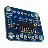
HX711 Module Pinout
When working with the HX711 Load cell amplifier, understanding the HX711 module pinout becomes crucial for successful load cell interfacing with Arduino and HX711 projects.
The HX711 features a well-organized 10-pin configuration that provides both load cell to the Arduino board connectivity and excitation power for the load cell itself, making it an ideal choice for digital scale project implementations.

Pin Configuration Details
Pin 1 (VCC) serves as the power supply input accepting voltage ranges from 2.6V to 5.5V, making it compatible with both 3.3V and 5V Arduino systems and ensuring reliable operation across different microcontroller platforms.
Pin 2 (GND) functions as the ground reference point for the entire module, providing the necessary return path for both power and signal circuits.
Pin 3 (DT - Data) acts as the serial data output line that transmits the 24-bit converted weight measurements from the HX711 to the microcontroller, typically connected to any available digital input pin on the Arduino.
Pin 4 (SCK - Serial Clock) receives the clock signal from the microcontroller to synchronize data transmission and control the HX711's operation modes including power-down functionality.
Pin 5 (E+) provides the positive excitation voltage to energize the load cell's Wheatstone bridge circuit, typically outputting the same voltage as the VCC supply for maximum load cell sensitivity.
Pin 6 (E-) supplies the negative excitation reference, completing the power circuit required for proper load cell operation and signal generation.
Pin 7 (A-) connects to the negative signal output from Channel A of the load cell, receiving the small voltage changes that represent weight measurements with high precision and minimal noise interference.
Pin 8 (A+) interfaces with the positive signal output from Channel A, working in conjunction with A- to create the differential signal that gets amplified and digitized by the HX711's internal circuitry.
Pin 9 (B-) provides connection for the negative signal input of optional Channel B, allowing for dual load cell configurations or differential measurement setups in advanced weighing applications.
Pin 10 (B+) completes the Channel B input circuit by accepting the positive signal from a second load cell, enabling more complex weighing systems that require multiple sensor inputs or enhanced accuracy through load cell redundancy.
Components Required for the Setup
Setting up your Arduino digital scale project requires several key components that work together to create a complete weighing system.
From my experience building various Arduino projects, having quality components makes all the difference in achieving reliable and accurate results.
Essential Components:
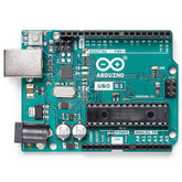
- Arduino Uno: The microcontroller that processes all the weight data
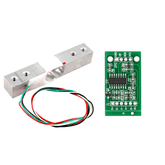
- HX711 Load Cell Module: The critical bridge between load cell and Arduino
- Load Cell (1kg to 200kg depending on application): The actual weight sensor
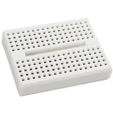
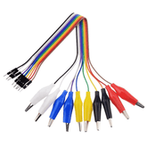
- Breadboard and Jumper Wires: For making connections during prototyping
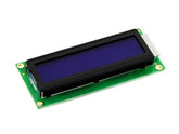
- 16x2 LCD Display (Optional): For displaying weight readings without computer connection
- Power Supply: 7-12V adapter for Arduino or USB power for testing
Wiring Diagram: Connecting Load Cell to Arduino using HX711
Understanding the proper wiring load cell connections is crucial for achieving accurate measurements in your weighing system.
The wiring process involves two main stages: connecting the load cell to the HX711 module and then connecting the HX711 to your Arduino board.
Load Cell to HX711 Connections:
The standard four-wire load cell uses a color-coded system that makes connections straightforward:
- Red Wire (E+): Connect to HX711 E+ terminal (Excitation positive)
- Black Wire (E-): Connect to HX711 E- terminal (Excitation negative)
- White Wire (A-): Connect to HX711 A- terminal (Signal negative)
- Green Wire (A+): Connect to HX711 A+ terminal (Signal positive)

HX711 to Arduino Connections:
The hx711 load cell amplifier interface with Arduino requires only four simple connections:
- VCC: Connect to Arduino 5V (or 3.3V for 3.3V boards)
- GND: Connect to Arduino GND
- DT (Data): Connect to Arduino Digital Pin 2
- SCK (Clock): Connect to Arduino Digital Pin 3
The polarity of the load cell wires isn't critical—if you accidentally swap the excitation wires (red/black) or signal wires (white/green), the system will still work, but you'll need to adjust the calibration factor in software. This forgiving design makes the initial setup much less stressful for beginners.
Step-by-Step Guide to Hardware Connections
Let me walk you through the complete hardware setup process that I've refined through numerous Arduino Uno with HX711 projects. Taking your time with these connections will save hours of troubleshooting later.
Step 1: Prepare Your Workspace
Start with a clean, well-lit workspace and gather all components. Ensure your Arduino is disconnected from power during all wiring steps. I always recommend using a small breadboard for initial prototyping, as it makes troubleshooting much easier than direct connections.
Step 2: Connect the Load Cell to HX711
Begin by carefully examining your load cell's wire colors. Most follow the standard color scheme, but I've encountered variations, so always double-check
Connect each wire firmly to the corresponding HX711 terminal:
- Locate the E+ and E- terminals on the HX711 module
- Connect the red wire (excitation positive) to E+
- Connect the black wire (excitation negative) to E-
- Find the A+ and A- terminals for signal connections
- Connect the green wire (signal positive) to A+
- Connect the white wire (signal negative) to A-
Step 3: Wire HX711 to Arduino
Now we'll establish the crucial connection between the load cell to the Arduino board:
- Connect HX711 VCC to Arduino 5V pin
- GND to Arduino GND pin
- DT (Data) to Arduino Digital Pin 2
- SCK (Clock) to Arduino Digital Pin 3
Step 4: Double-Check All Connections
Before powering up, carefully verify each connection against the wiring diagram. Pay special attention to power connections—incorrect wiring here can damage components. I always use a multimeter to verify continuity when in doubt.
Step 5: Secure the Load Cell
For accurate measurements, the load cell must be properly mounted. The bar-type load cells have specific mounting requirements—secure one end firmly to a stable surface and attach a platform to the other end where weights will be placed.
The direction of deflection matters, so ensure the load cell's arrow indicator points in the correct direction for your application.
Installing the HX711 Arduino Library
Getting the right HX711 Library installed is essential for communicating with your weighing system. After testing various libraries over the years, I've found that choosing the right one can significantly impact your project's performance and ease of use.
Recommended Library Installation
The most reliable approach is using the Arduino Library Manager:
- Open Arduino IDE and navigate to Sketch > Include Library > Manage Libraries
- Search for "HX711 Arduino Library" in the search box
- Install the library by Bogdan Necula - this is the most popular and well-maintained option
- Wait for installation to complete - the IDE will automatically handle dependencies
Verifying Installation
After installation, verify the library is working:
- Restart Arduino IDE to ensure proper library registration
- Navigate to File > Examples and look for HX711 examples
- Open a basic example to confirm the library functions are accessible
- Check for any compilation errors when loading example code
The library installation process is straightforward, but I always recommend restarting the IDE after installation to avoid any potential issues with library recognition.
Arduino Code for Reading Load Cell Data
Now comes the exciting part, writing code that transforms your Arduino weight sensor into a functional measuring device.
#include "HX711.h"

// Define pins for HX711
const int LOADCELL_DOUT_PIN = 2;
const int LOADCELL_SCK_PIN = 3;

// Create HX711 object
HX711 scale;

void setup() {
  // Initialize serial communication
  Serial.begin(9600);

  // Initialize the scale
  scale.begin(LOADCELL_DOUT_PIN, LOADCELL_SCK_PIN);

  Serial.println("HX711 Demo");
  Serial.println("Initializing the scale");

  // Reset the scale to 0
  scale.set_scale();
  scale.tare();

  Serial.println("After setting up the scale:");
  Serial.print("read: \t\t");
  Serial.println(scale.read());
  Serial.print("read average: \t\t");
  Serial.println(scale.read_average(20));
  Serial.print("get value: \t\t");
  Serial.println(scale.get_value(5));
  Serial.print("get units: \t\t");
  Serial.println(scale.get_units(5), 1);

  scale.set_scale(2280.f);    // Calibration factor (to be determined)
  scale.tare();               // Reset to zero

  Serial.println("After setting up calibration:");
  Serial.print("read: \t\t");
  Serial.println(scale.read());
  Serial.print("read average: \t\t");
  Serial.println(scale.read_average(20));
  Serial.print("get value: \t\t");
  Serial.println(scale.get_value(5));
  Serial.print("get units: \t\t");
  Serial.println(scale.get_units(5), 1);

  Serial.println("Readings:");
}

void loop() {
  // Check if HX711 is ready
  if (scale.is_ready()) {
    Serial.print("Weight: ");
    Serial.print(scale.get_units(), 1);
    Serial.println(" grams");
  } else {
    Serial.println("HX711 not found.");
  }

  delay(1000);
}
Code Explanation
This code demonstrates the essential functions for Load cell interfacing with Arduino and HX711:
- scale.begin(): Initializes communication with the HX711 module
- scale.set_scale(): Sets the calibration factor (crucial for accurate readings)
- scale.tare(): Zeros the scale by removing any initial offset
- scale.get_units(): Returns the calibrated weight reading
- scale.is_ready(): Checks if the HX711 has new data available
The Calibrating HX711 with Arduino process requires determining the correct scale factor, which we'll cover in the next section. The value 2280.f in the code is just a placeholder—your specific setup will require a different calibration factor.
Calibrating the Load Cell with HX711 and Arduino
Calibration is where your Arduino project transforms from a basic sensor reader into a precision measuring instrument. Through extensive testing with various load cells, I've developed a systematic approach that consistently delivers accurate results.
Step 1: Determine the Raw Reading
First, we need to establish what the HX711 reads without any calibration:
void setup() {
  Serial.begin(9600);
  scale.begin(LOADCELL_DOUT_PIN, LOADCELL_SCK_PIN);

  scale.set_scale();
  scale.tare();  // Reset to zero

  Serial.println("Remove all weight from scale");
  Serial.println("After readings stabilize, place known weight on scale");
  Serial.println("Readings:");
}

void loop() {
  Serial.print("Reading: ");
  Serial.println(scale.get_value(), 1);
  delay(500);
}
Step 2: Calculate Calibration Factor
The calibration process requires a known weight (I recommend using a 100g or 500g calibration weight):
- Record the zero reading with nothing on the scale
- Place your known weight and record the new reading
- Calculate the difference between loaded and unloaded readings
- Divide the difference by the known weight to get your calibration factor
Example Calculation:
- Unloaded reading: 8,500
- Loaded reading with 100g weight: 108,500
- Difference: 100,000
- Calibration factor: 100,000 ÷ 100g = 1,000
Step 3: Apply Calibration Factor
void setup() {
  Serial.begin(9600);
  scale.begin(LOADCELL_DOUT_PIN, LOADCELL_SCK_PIN);

  scale.set_scale(1000);  // Use your calculated calibration factor
  scale.tare();           // Reset to zero

  Serial.println("Scale ready for accurate measurements");
}
Step 4: Verify Accuracy
Test your calibration with multiple known weights to ensure accuracy across the entire measurement range. I typically test at 25%, 50%, 75%, and 100% of the load cell's capacity to verify linear response
Displaying Weight on the Serial Monitor
The Serial Monitor provides an excellent interface for monitoring your scale's performance and debugging any issues that arise. Here's how to Connect load cell to Arduino using HX711 with comprehensive serial output.
#include "HX711.h"

const int LOADCELL_DOUT_PIN = 2;
const int LOADCELL_SCK_PIN = 3;

HX711 scale;
float calibration_factor = 1000; // Adjust based on your calibration

void setup() {
  Serial.begin(9600);
  Serial.println("========================================");
  Serial.println("      HX711 Load Cell Scale Demo       ");
  Serial.println("========================================");

  scale.begin(LOADCELL_DOUT_PIN, LOADCELL_SCK_PIN);

  Serial.println("Initializing scale...");
  scale.set_scale();
  scale.tare();

  Serial.println("Setup complete!");
  Serial.println("Place weights on scale for measurement");
  Serial.println("========================================");

  // Apply calibration
  scale.set_scale(calibration_factor);
  scale.tare();
}

void loop() {
  if (scale.is_ready()) {
    float weight = scale.get_units(10); // Average of 10 readings

    Serial.print("Weight: ");
    Serial.print(weight, 2);
    Serial.print(" g | ");
    Serial.print(weight/1000, 3);
    Serial.print(" kg | ");
    Serial.print(weight*0.00220462, 3);
    Serial.println(" lbs");

    // Display raw reading for debugging
    Serial.print("Raw reading: ");
    Serial.println(scale.read());

    Serial.println("------------------------");
  } else {
    Serial.println("Scale not ready - check connections");
  }

  delay(2000);
}
Serial Monitor Features
This enhanced code provides:
- Multiple unit displays (grams, kilograms, pounds) for versatility
- Raw reading output for calibration and debugging purposes
- Connection status monitoring to identify hardware issues
- Formatted output for easy reading and data logging
- Averaged readings to reduce noise and improve accuracy
The Serial Monitor becomes an invaluable tool for troubleshooting, allowing you to see exactly what the HX711 is detecting and how your calibration affects the final measurements.
Conclusion
Throughout this comprehensive guide, we've transformed what initially might have seemed like a complex electronic puzzle into a straightforward, achievable project.
The HX711 load cell module proves itself as an outstanding solution for Arduino-based weighing applications, offering professional-grade accuracy in a package that's accessible to makers of all skill levels.
From understanding the fundamental principles of load cell operation to implementing precise calibration routines, we've covered every aspect necessary to build a reliable digital weighing system.
The modular nature of this setup means you can start with basic weight measurements and expand into sophisticated applications like IoT monitoring, automated sorting systems, or industrial process control.


