How to Connect a Temperature Sensor to Micro:bit V2
Summary
Learning how to connect a temperature sensor to Micro:bit V2 opens up endless possibilities for environmental monitoring and hands-on STEM projects.
The BBC Micro:bit V2 is a powerful educational tool that allows students and hobbyists to explore electronics, programming, and data collection in an accessible way.
When paired with an external temperature sensor like the DHT11, you can build sophisticated projects ranging from weather stations to smart home automation systems.
This tutorial will guide you through every step of connecting and programming a temperature sensor with your Micro:bit V2 board.

How Temperature Sensors Work
Temperature sensors are fascinating devices that convert thermal energy into electrical signals that microcontrollers can understand and process.
The DHT11 sensor, one of the most popular choices for beginner-friendly projects, uses a specialized component called a Negative Temperature Coefficient (NTC) thermistor to detect temperature changes.

Understanding the Temperature Detection Mechanism:
- When the surrounding temperature rises, the resistance within the thermistor decreases proportionally
- This change in resistance is measured by the sensor's internal chip to determine the precise temperature
- The sensor operates within a voltage range of 3.3V to 5V, making it fully compatible with the Micro:bit's power specifications
- Temperature measurements range from 0°C to 50°C with an accuracy of ±2°C
The DHT11 doesn't only measure temperature. It's actually a dual-function sensor that also monitors humidity levels using a capacitive humidity sensing element.
For humidity detection, the sensor employs a polymer material positioned between two electrodes. When environmental moisture levels change, this polymer's conductivity changes, causing the resistance between the electrodes to rise or fall.
Communication Protocol Details:
Communication between the DHT11 and your Micro:bit happens through a unique single-wire digital protocol. The entire communication process follows three distinct steps:
- Your Micro:bit sends a start pulse by pulling the data line low for at least 18 milliseconds
- The DHT11 responds with its own pulse—low for 54 microseconds, then high for 80 microseconds—to acknowledge it received the request
- The sensor transmits 40 bits of data containing humidity values, temperature values, and a checksum for error verification
This digital output eliminates the need for complex analog-to-digital conversion circuits, making the DHT11 perfect for educational projects. The sensor has a sampling rate of 1Hz, meaning it can provide fresh readings once per second.
While these specifications make it ideal for basic environmental monitoring and learning projects, professional applications requiring higher precision might opt for the more accurate DHT22 sensor.
Components You'll Need for This Project
Before diving into interfacing a temperature sensor to Micro:bit V2, gather all the necessary components to ensure a smooth build process.
Essential Hardware Components:
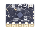
- Micro:bit V2 Board: The heart of your project, featuring a 25-pin edge connector for interfacing with external devices
- Micro:bit Sensor Shield: Often called the Keyestudio expansion board, which breaks out the Micro:bit's pins into standard breadboard-friendly connectors
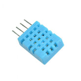
- DHT11 Temperature Sensor Module: Typically comes mounted on a small breakout board with three pins labeled S (Signal), V (Voltage), and G (Ground)
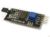
- LCD I2C 1602 Display Module: Uses the I2C communication protocol for displaying temperature readings
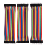
- Jumper Wires: Female-to-female jumper wires work best when connecting to the sensor shield's pins
- Micro USB Cable: Required to program your Micro:bit and can also provide power during testing
- Battery Pack (Optional): For portable operation, allowing your temperature monitoring system to work independently of a computer connection
The expansion board is essential because it makes wiring much more manageable and provides clearly labeled pin connections.
Some DHT11 modules include a built-in pull-up resistor on the data line, which simplifies your circuit—always check your specific module's documentation.
Understanding the I2C Display:
The I2C interface is a serial protocol that requires only two data lines—SDA (Serial Data) and SCL (Serial Clock)—plus power and ground connections. Key features include:
- Only uses two pins on your Micro:bit, preserving GPIO pins for other sensors
- Typical I2C LCD uses address 0x27, though some modules may use 0x3F
- Can scan for the address using I2C scanning code if needed
- Allows multiple I2C devices to share the same bus using different addresses
Having a breadboard can be helpful for organizing connections, though it's not strictly necessary when using a sensor shield. For this project, you won't need additional resistors or complex components when using a DHT11 module with the integrated pull-up resistor.
Circuit Diagram: Connecting a Temperature Sensor to Micro:bit V2
The circuit diagram provided illustrates a complete temperature monitoring system that demonstrates how to connect a temperature sensor to Micro:bit V2 alongside an I2C LCD display for real-time data visualization.

Main Components in the Diagram:
At the top of the diagram, you can see the Micro:bit V2 board with its distinctive 5x5 LED matrix and edge connector featuring multiple gold pins labeled 0, 1, 2, 3V, and GND.
The Micro:bit connects to a Keyestudio sensor shield shown at the bottom left, which expands the board's connectivity options and provides clearly organized pin headers.
DHT11 Temperature Sensor Connections:
The DHT11 temperature sensor module appears in the upper right corner, displaying its characteristic blue sensing element and three connection pins. According to the wiring shown:
- The signal pin (green wire) connects to one of the digital GPIO pins on the sensor shield
- The red wire carries the power supply (3.3V or 5V) to the sensor
- The blue or black wire connects to ground
- This three-wire connection is all you need to establish communication between the DHT11 and your Micro:bit
I2C LCD Display Wiring:
The I2C LCD module and its adapter board are positioned at the bottom right of the diagram. The I2C interface simplifies the display connection significantly—instead of requiring 16 pins like a standard parallel LCD, it needs only four connections:
- SDA pin connects to pin 20 (P20) on the Micro:bit
- SCL pin connects to pin 19 (P19)
- VCC connects to 5V power supply
- GND connects to ground
These are the dedicated I2C communication pins on the Micro:bit V2, internally connected to onboard sensors like the accelerometer and compass.
Multiple colored wires in the diagram show the complete signal path from the Micro:bit through the sensor shield to both the DHT11 sensor and the LCD display.
The parallel routing of these wires demonstrates that both devices can operate simultaneously on the same Micro:bit without interference—the DHT11 uses a digital GPIO pin while the LCD uses the I2C bus.
This multi-component configuration showcases a practical example of interfacing temperature sensor with Micro:bit in a real-world application where sensor data is collected and immediately displayed for monitoring.
Step-by-Step Guide: How to Connect a Temperature Sensor to Micro:bit V2
Follow this comprehensive guide to successfully build your temperature sensor with Micro:bit project.
Step 1: Prepare Your Workspace and Assemble the Sensor Shield
Begin by preparing your workspace and components for connecting DHT11 sensor to Micro:bit.
Assembly Instructions:
- Clear a clean, static-free workspace with good lighting
- Gather all components listed in the previous section
- Carefully insert your Micro:bit V2 board into the edge connector slot on the Keyestudio sensor shield
- Ensure the LED display faces outward and all pins are properly aligned
- The shield should fit snugly without forcing—if you encounter resistance, double-check the alignment before applying pressure
Once secured, the sensor shield transforms your Micro:bit into a more accessible platform for prototyping and experimentation. The clearly labeled pin headers on the shield make it much easier to identify where to connect your sensors and displays.
Step 2: Connect the DHT11 Temperature Sensor
Next, connect the DHT11 temperature sensor to the sensor shield using jumper wires.
Wiring the DHT11 Module:
- Locate three adjacent pins on the shield's GPIO section—you'll typically use one of the digital pins like P0, P1, or P2 for the signal connection
- Connect the DHT11's signal pin (S) to your chosen digital pin (for example, P0) using a jumper wire
- Connect the voltage pin (V or VCC) to the 3.3V or 5V power rail on the shield
- Connect the ground pin (G or GND) from the DHT11 to any GND pin on the shield
- Make sure these connections are firm and secure to prevent intermittent readings that can frustrate debugging efforts later
For this project involving interfacing temperature sensor with Micro:bit, you won't need additional resistors or complex components when using a DHT11 module with the integrated pull-up resistor.
Always verify your specific DHT11 module's pinout diagram, as some manufacturers may arrange pins differently.
Step 3: Wire the I2C LCD Display
Now you'll set up the I2C LCD display for real-time temperature monitoring.
LCD Connection Details:
The LCD module has four pins that need connecting: SDA, SCL, VCC, and GND. Follow these steps:
- Using female-to-female jumper wires, connect the LCD's SDA pin to P20 on the sensor shield
- Connect the SCL pin to P19—these are the Micro:bit's dedicated I2C communication pins
- Connect the LCD's VCC pin to the 5V power supply on the shield (the LCD typically requires 5V rather than 3.3V for proper backlight operation)
- Connect the LCD's GND pin to a ground connection on the shield
- Double-check all four connections before proceeding, as incorrect I2C wiring can prevent the display from initializing
The beauty of I2C communication is that it only uses two data pins regardless of how complex the display is, leaving plenty of GPIO pins available for additional sensors in future Micro:bit projects for beginners.
Step 4: Program Your Micro:bit Using MakeCode
With the hardware assembled, it's time to program your Micro:bit for reading temperature data from Micro:bit.
Setting Up the Programming Environment:
- Connect your Micro:bit to your computer using a Micro USB cable
- Navigate to the MakeCode editor at makecode.microbit.org in your web browser
- Create a new project and give it a meaningful name like "Temperature Monitor"
Adding Required Extensions:
For this project involving external sensors and displays, you'll need to add extensions:
- Click "Extensions" in the MakeCode toolbox (gear icon or advanced section)
- Search for "DHT11" or "DHT" to find the DHT11 sensor library
- Click on the extension to add it to your project
- Similarly, search for "LCD" or "I2C LCD" to find and add the LCD1602 I2C extension
- These extensions provide ready-made blocks for temperature sensor with Micro:bit projects, eliminating the need to write low-level communication protocols from scratch
Writing the Code:
In your code, implement the following logic for temperature monitoring with Micro:bit:
- Start by initializing the LCD display with the "initialize LCD" block from the LCD extension
- Specify the I2C address (typically 0x27) and the display size (16 columns, 2 rows)
- Inside a "forever" loop, use the DHT11 extension blocks to query the temperature and humidity values from your sensor
- Specify the pin you connected it to (for example, P0)
- Store these readings in variables like "temp" and "humid"
- Use the LCD display blocks to show the data on specific rows and columns of the screen
- Display "Temp:" and the temperature value on row 1
- Display "Humid:" with the humidity value on row 2
- Add a pause block (1000 milliseconds) at the end of the loop to refresh readings every second, matching the DHT11's sampling rate
Step 5: Upload and Test Your Program
Once your code is complete, transfer it to your Micro:bit and verify operation.
Deployment Steps:
- Click the "Download" button in MakeCode to compile your program
- A .hex file will download to your computer
- Drag and drop the .hex file onto the MICROBIT drive that appears when you connect the board
- The Micro:bit will automatically flash the new program and restart
- The yellow LED on the back of the Micro:bit will flash during the upload process
Testing and Troubleshooting:
You should immediately see temperature and humidity readings appear on the LCD display, updating every second. This demonstrates practical environmental data logging in action:
- If the display shows garbled characters or nothing at all, verify your I2C address is correct
- You can use I2C scanning code to detect the actual address if needed
- If the DHT11 readings show zeros or errors, check your signal wire connection and ensure you specified the correct pin in your code
- Verify all power and ground connections are secure
- Try placing your hand near the DHT11 sensor—you should see the temperature reading increase from your body heat
This complete system demonstrates how to program Micro:bit to read temperature and serves as an excellent foundation for more advanced IoT projects with Micro:bit.
For students and educators, this project exemplifies hands-on STEM education projects that combine electronics, programming, and real-world applications.
Expansion Ideas:
You can expand upon this foundation by:
- Adding data logging to store temperature readings over time on a computer via serial communication
- Creating threshold-based alerts when temperature exceeds certain limits (display warnings or sound a buzzer)
- Transmitting data wirelessly to another Micro:bit using the radio function for remote monitoring
- Recording minimum and maximum temperatures throughout the day
- Adding more sensors to create a complete weather station
These extensions transform a simple temperature sensor project into a comprehensive exploration of Micro:bit tutorials for students that teach fundamental concepts in embedded systems.
Conclusion
Mastering how to program Micro:bit to read temperature through external sensors like the DHT11 empowers you to build sophisticated environmental monitoring systems with minimal components and straightforward wiring.
This tutorial has walked you through understanding how temperature sensors convert physical phenomena into digital data, assembling the necessary hardware components, interpreting a complete circuit diagram, and writing functional code to display real-time readings.
These building blocks form the foundation for countless other projects, from automated climate control systems to agricultural monitoring stations.
As you continue exploring the possibilities of the Micro:bit ecosystem, remember that the best learning happens through experimentation and iteration, so don't hesitate to modify this project to suit your own creative ideas and practical needs.


