Bluetooth-Controlled Car with Arduino and HC-05 Module
Summary
In today's digital world, robotics projects have become an essential part of STEM education, providing students with hands-on experience in electronics, programming, and wireless communication.
One of the most popular and engaging projects for school students is building a BLUETOOTH CONTROLLED CAR using Arduino and the HC-05 module.
This project perfectly combines hardware assembly with software programming, making it an ideal introduction to the world of robotics and IoT

What is a Bluetooth Controlled Car?
A Bluetooth controlled car is a wireless robotic vehicle that can be operated remotely using a smartphone or tablet via Bluetooth communication.
This innovative robotics project allows students to control the car's movements—forward, backward, left, and right—through a simple mobile application, eliminating the need for physical remote controls or wired connections.
Components Required
To build this exciting DIY project, you'll need the following components:
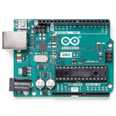
- Arduino Uno: The brain of the project - a microcontroller that processes commands
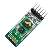
- HC-05 Bluetooth Module: Creates wireless communication between your phone and Arduino
- DC Motors (2): Provide power to move the wheels and propel the car
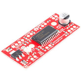
- L298N Motor Driver: Safely manages high current needed by motors based on Arduino signals
- Wheel Caster Set (2): Ensures proper steering and maneuverability
- Chassis: The base structure that holds all components together
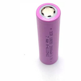
- Power Source: Rechargeable batteries (Li-ion recommended) for mobile operation
- Jumper Wires: Connect all electronic components
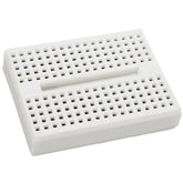
- Breadboard (Optional): Useful for circuit prototyping
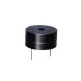
- Buzzer: Adds audio feedback for enhanced user experience
- Smartphone: With Bluetooth capability to control the car
Circuit Connections and Wiring
Here's the detailed step-by-step connection guide for your Bluetooth controlled car project:

Main Components Layout
The diagram illustrates the complete circuit architecture with the L298N Motor H-Bridge as the central control unit, connecting the Arduino microcontroller to the DC gear motors and servo motors.
Arduino to L298N Motor Driver Connections:
- Digital Pin 12 → IN1 (Motor A control)
- Digital Pin 11 → IN2 (Motor A control)
- Digital Pin 10 → IN3 (Motor B control)
- Digital Pin 9 → IN4 (Motor B control)
- 5V Pin → VCC (Logic power supply)
- GND Pin → Ground (Common ground)
L298N Motor Driver to DC Gear Motors:
- Left DC Gear Motor → Motor A terminals (OUT1 and OUT2)
- Right DC Gear Motor → Motor B terminals (OUT3 and OUT4)
- Motor Power Supply → 12V input terminal on L298N
Power Supply Connections:
- Battery Pack (7.4V Li-ion recommended) connects to:
- Positive terminal → VIN on Arduino and motor power input on L298N
- Negative terminal → Common ground for entire circuit
HC-05 Bluetooth Module Connections:
- VCC → Arduino 5V pin
- GND → Arduino Ground pin
- TX → Arduino Digital Pin 2 (Software Serial RX)
- RX → Arduino Digital Pin 3 (Software Serial TX)
Additional Servo Motor Integration:
As shown in the diagram, if you're adding servo motors for enhanced functionality:
- DC Servo Motor → Connect to Arduino PWM pins (Pin 5 and Pin 6)
- Power lines → 5V and Ground from Arduino
Wire Color Coding (As Per Diagram)
Following the standard color coding shown in the circuit diagram:
- Red wires: Positive power connections (+5V, +12V)
- Black wires: Ground/negative connections
- Green wires: Digital signal lines to motor driver
- Blue wires: Bluetooth module data connections
- Orange/Yellow wires: Motor control signals
Arduino Code
Here's the complete code for your Bluetooth controlled car:
#include

// Define motor control pins
#define IN1 12
#define IN2 11
#define IN3 10
#define IN4 9

// Create SoftwareSerial object for Bluetooth communication
SoftwareSerial bluetooth(2, 3); // RX, TX

char command;

void setup() {
  // Initialize serial communication
  Serial.begin(9600);
  bluetooth.begin(9600);

  // Set motor pins as outputs
  pinMode(IN1, OUTPUT);
  pinMode(IN2, OUTPUT);
  pinMode(IN3, OUTPUT);
  pinMode(IN4, OUTPUT);

  // Initialize all motors to stop
  stopMotors();

  Serial.println("Bluetooth Car Ready!");
}

void loop() {
  // Check if data is available from Bluetooth
  if (bluetooth.available()) {
    command = bluetooth.read();
    Serial.println(command);

    // Execute commands based on received data
    switch(command) {
      case '1': // Forward
        moveForward();
        break;
      case '2': // Backward
        moveBackward();
        break;
      case '3': // Left
        turnLeft();
        break;
      case '4': // Right
        turnRight();
        break;
      case '5': // Stop
        stopMotors();
        break;
      default:
        stopMotors();
        break;
    }
  }
}

void moveForward() {
  digitalWrite(IN1, HIGH);
  digitalWrite(IN2, LOW);
  digitalWrite(IN3, HIGH);
  digitalWrite(IN4, LOW);
}

void moveBackward() {
  digitalWrite(IN1, LOW);
  digitalWrite(IN2, HIGH);
  digitalWrite(IN3, LOW);
  digitalWrite(IN4, HIGH);
}

void turnLeft() {
  digitalWrite(IN1, LOW);
  digitalWrite(IN2, HIGH);
  digitalWrite(IN3, HIGH);
  digitalWrite(IN4, LOW);
}

void turnRight() {
  digitalWrite(IN1, HIGH);
  digitalWrite(IN2, LOW);
  digitalWrite(IN3, LOW);
  digitalWrite(IN4, HIGH);
}

void stopMotors() {
  digitalWrite(IN1, LOW);
  digitalWrite(IN2, LOW);
  digitalWrite(IN3, LOW);
  digitalWrite(IN4, LOW);
}
The Working Process
The following 5 steps describes the core working mechanism:
- Command Transmission: When you press a directional button in the smartphone app, specific data is transmitted via Bluetooth
- Data Reception: The HC-05 module receives this data and forwards it to the Arduino
- Signal Processing: Arduino processes the received command using a switch-case structure
- Motor Control: Based on the command, Arduino sends appropriate signals to the L298N motor driver
- Movement Execution: The motor driver controls the DC motors to achieve the desired movement
Command Mapping:
- Forward → '1'
- Backward → '2'
- Left → '3'
- Right → '4'
- Stop → '5'


