Guide to Simple Water Level Indicator Project
Summary
If you’ve ever dealt with a water tank, you know the frustration of not knowing how much water is left.
The unexpected overflow that wastes precious water or the inconvenience of a tank running dry are all too common.
But what if you could solve this with a simple, smart, and fun DIY project?
In this walkthrough, we'll cover the key components, provide a detailed step-by-step guide, and show you the code that brings it all to life.
Let's find out if the Arduino water level indicator is the perfect weekend project for your home.

What is an Arduino Water Level Indicator?
It’s an electronic device that uses an Arduino microcontroller as its brain to read data from a water level sensor and display the results in an easy-to-understand way.
Instead of relying on complex analog circuits with multiple transistors, this version centralizes the logic into a single, programmable board.
Step – by – Step Guide:
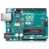
An Arduino Board (The Brain): An Arduino Uno is the perfect choice for this project. It has all the necessary input/output pins and is incredibly easy to work with, making it the reliable centerpiece of our build.
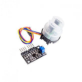
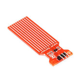
Water Level Sensor Module (The Senses): This is the key component that detects the water. It’s a specialized sensor with exposed conductive traces. As water rises and covers more of the traces, its electrical properties change, sending a clear signal back to the Arduino.
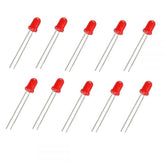
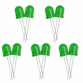
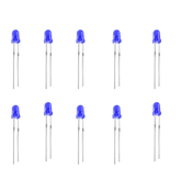
LEDs (The Visuals): We'll use 3 or 4 LEDs in different colors. A common setup is:
- Yellow LED for low level (e.g., 25%)
- Green LED for medium level (e.g., 50%)
- Blue LED for high level (e.g., 75%)
- You could also add a Red LED for the "full" alert.
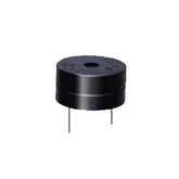
Piezo Buzzer (The Alarm): To prevent overflows, a simple 9V Piezo Buzzer will act as our audible alarm. When the water reaches the highest point, the Arduino will make it beep, giving you a clear alert.
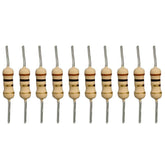
Resistors (The Protectors): You will need one 220Ω resistor for each LED you use. These small but crucial components protect your LEDs from receiving too much current from the Arduino, ensuring they don't burn out.
Step 1: The Wiring

First, we'll connect all our components on the breadboard.
- Connect the Sensor: Connect the sensor's Signal pin to A0 on the Arduino, the '+' pin to 5V, and the '–' pin to GND.
- Connect the LEDs: Wire each LED (through a 220Ω resistor) to a separate digital pin on the Arduino (e.g., pins 7, 8, and 9). Connect the other leg to GND.
- Connect the Buzzer: Connect the buzzer's positive pin to another digital pin (e.g., pin 10) and its negative pin to GND.
Step 2: Upload the Code
Copy the following code into your Arduino IDE and upload it to your board. This code reads the sensor and controls the indicators based on the water level.
const int sensorPin = A0;
const int yellowLedPin = 7;
const int greenLedPin = 8;
const int blueLedPin = 9;
const int buzzerPin = 10;

void setup() {
  pinMode(yellowLedPin, OUTPUT);
  pinMode(greenLedPin, OUTPUT);
  pinMode(blueLedPin, OUTPUT);
  pinMode(buzzerPin, OUTPUT);
  Serial.begin(9600);
}

void loop() {
  int sensorValue = analogRead(sensorPin);
  Serial.println(sensorValue);

  // Reset all indicators
  digitalWrite(yellowLedPin, LOW);
  digitalWrite(greenLedPin, LOW);
  digitalWrite(blueLedPin, LOW);
  noTone(buzzerPin);

  // Adjust these values after testing!
  if (sensorValue > 300) { digitalWrite(yellowLedPin, HIGH); }
  if (sensorValue > 450) { digitalWrite(greenLedPin, HIGH); }
  if (sensorValue > 600) { digitalWrite(blueLedPin, HIGH); }
  if (sensorValue > 750) { tone(buzzerPin, 1000); }

  delay(500);
}
Step 3: Test and Calibrate
With the code running, dip the water sensor into a container of water and open the Arduino's Serial Monitor.
Watch the sensorValue numbers change as you raise and lower the sensor. Note down the values for the different levels you want to mark.
Finally, update the numbers in the if statements in the code to match your noted values. This calibrates your system perfectly.
The performance of this Arduino water level indicator is both reliable and accurate, providing instant feedback as the water level changes.
Conclusion
So, what's the final verdict on the Arduino water level indicator? After walking through the build, I can confidently say that this is one of the best introductory projects for anyone interested in home automation or Arduino.
It's practical, affordable, and incredibly satisfying to see it work.


