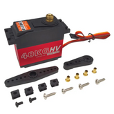
What is a Servo Motor? ( Guide to Servo Motor Working)
Summary
If you've ever wondered what a servo motor is and how it functions, this blog is your gateway to the world of this fascinating device. Discover the inner workings and principles that make servo motors the perfect choice for precise and controlled motion. From exploring the mechanism behind servo motor operation to learning about their seamless integration with microcontrollers, this article provides a comprehensive understanding of servo motors. Whether you're a tech enthusiast or an engineer seeking to expand your knowledge, dive into this informative blog and unravel the secrets of servo motor control. Click now to unlock the potential of servo motors!
What is a Servo Motor?
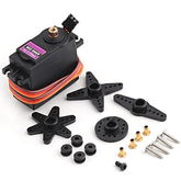
A Servo Motor is a type of motor that is used to control the angular position of a shaft. It is a closed-loop control system that consists of a motor, a gear train, and a feedback sensor. The motor rotates the shaft to a specific position, and the feedback sensor ensures that the shaft stays at that position.

The motor receives a control signal from a microcontroller or other controller, which tells it the desired angular position of the shaft. The servo motor then rotates the shaft to the desired position and holds it there. The feedback sensor, typically a potentiometer, provides feedback on the actual angular position of the shaft to the controller. The controller then makes adjustments as necessary to keep the shaft at the desired position.
Servo motors find widespread usage in robotics, automation systems, and various applications that demand accurate control over the angular position of a shaft. These motors are usually compact in size, possess a favorable torque-to-weight ratio, are reasonably affordable, and offer ease of control.
Servo Motor Working Mechanism
The servo motor working mechanism is based on the control system called the "closed-loop control system". The closed-loop control system has a feedback mechanism that compares the actual position of the servo motor with the desired position.
The servo motor receives a control signal from a microcontroller or other controller, which tells it the desired angular position of the shaft. The motor then rotates the shaft to the desired position and holds it there. The feedback sensor, typically a potentiometer, provides feedback on the actual angular position of the shaft to the controller.
The controller compares the actual position of the servo motor with the desired position and generates an error signal. This error signal is used to adjust the motor's position so that it can reach the desired position.
When it comes to a PWM signal, the position of the servo motor is controlled by the duty cycle of the PWM signal. The servo motor's position is directly proportional to the duty cycle. Alternatively, in the case of an analog voltage, the voltage level is employed to control the position of the servo motor.
To summarize, the working mechanism of a servo motor relies on a closed-loop control system that utilizes a feedback sensor. This system continuously compares the actual position of the servo motor with the desired position and makes necessary adjustments to ensure the shaft remains at the desired position.
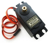
Check out TowerPro MG996R Servo Motor – The Best 180° Metal Gear Servo
Servo Motor Working Principle
A motor (either DC or AC), a potentiometer, a gear assembly, and a controlling circuit make up a servo. First, we employ a gear arrangement to lower the motor's RPM and boost its torque. Imagine that the potentiometer knob is set so that, while the servo motor shaft is in its original position, no electrical signal is produced at the potentiometer's output port. The error detection amplifier's second input terminal is now supplied with an electrical signal. Now, a feedback mechanism will process the difference between these two signals—one coming from the potentiometer and the other coming from external sources—and deliver output in the form of an error signal. This erroneous signal serves as the motor's input, and the motor begins to rotate. Now that the potentiometer and motor shaft are attached, a signal will be produced by the potentiometer as the motor rotates.
Consequently, the output feedback signal of the potentiometer changes as its angular position does. After some time, the potentiometer's position reaches a point where its output matches the supplied external signal. Because there is no distinction between the externally supplied signal and the signal generated at the potentiometer in this state, there will be no output signal from the amplifier to the motor input, and the motor will stop turning.
Interfacing Servo Motors with Microcontrollers
Servo motors can be easily interfaced with microcontrollers using a simple control signal. The control signal is typically a PWM signal, which is generated by the microcontroller. The PWM signal controls the position of the servo motor by adjusting the duty cycle of the signal. The servo motor's position is proportional to the duty cycle of the PWM signal. Then the Vcc, Gnd is given to 5v, Ground of microcontroller. There is an example below which depicts the interfacing of the Servo motor with Arduino.

Controlling Servo Motor
Controlling the servo motor is done using the signal terminal and controlling it by varying the PWM. The control wires offer PWM (Pulse with Modulation), which is used to drive the servo motor. There are three different pulse ranges: minimum, maximum, and repetition rate. A servo motor's neutral state allows it to turn 90 degrees in any direction. Every 20 milliseconds (ms), the servo motor expects to receive a pulse; the pulse's duration determines how far the motor will turn. For example, when a 1.5ms pulse is sent to the servo motor, it will rotate to the 90° position. If the pulse duration is shorter than 1.5ms, the shaft will move to the 0° position. Conversely, if the pulse duration is longer than 1.5ms, the servo motor will turn to the 180° position.

The duration of the pulse applied to the servo motor's Control PIN determines the angle at which it rotates, according to the PWM (Pulse Width Modulation) concept. The basic components of a servo motor are a DC motor, a variable resistor (potentiometer), and some gears. Gears transform a DC motor's high-speed force into torque. To determine the angle and stop the DC motor at the necessary angle, the potentiometer is linked to the servo's output shaft.
Conclusion
A servo motor is a rotary actuator that utilizes feedback to regulate the angular position of a shaft. It comprises a motor, a gear train, and a feedback sensor. The fundamental principle behind the operation of a servo motor is a closed-loop control system. This system constantly compares the current position of the servo motor with the intended position, and accordingly makes any necessary adjustments to maintain the shaft at the desired position. Servo motors can be easily interfaced with microcontrollers and controlled using a PWM signal or analog voltage.
If you appreciate our work don't forget to share this post and leave your opinion in the comment box.
Please do check out other blog posts about Popular electronics
Make sure you check out our wide range of products and collections (we offer some exciting deals!)
Frequently Asked Questions
1. How does a servo motor works?
A servo motor is an electromechanical device that operates based on the principle of closed-loop control. It is designed to provide precise control over angular or linear position, velocity, and acceleration. Here's how a servo motor works:
1. Structure: A servo motor consists of a DC motor, a position feedback sensor (usually a potentiometer or an encoder), a control circuit, and a gearbox (if required). The motor converts electrical energy into mechanical energy, while the position feedback sensor detects the actual position of the motor shaft.
2. Closed-loop system: The servo motor operates as part of a closed-loop control system. It means that it continuously receives feedback about the actual position of the motor shaft and compares it with the desired position.
3. Control circuit: The control circuit processes the feedback information and generates an error signal that represents the difference between the desired position and the actual position. Based on this error signal, the control circuit adjusts the motor's output to minimize the error and bring the motor shaft to the desired position.
4. Pulse Width Modulation (PWM): To control the servo motor's position, a control signal in the form of Pulse Width Modulation (PWM) is used. The control signal is typically a square wave with a fixed frequency (often around 50 Hz) and a variable pulse width. The pulse width determines the position the servo motor should move to.
5. Feedback adjustment: The control circuit adjusts the pulse width of the control signal based on the error signal. By increasing or decreasing the pulse width, the control circuit controls the motor's speed and direction to minimize the error and reach the desired position.
6. Position holding: Once the servo motor reaches the desired position, the control circuit continuously monitors the position feedback and makes small adjustments to maintain the motor shaft in the commanded position. This feature allows servo motors to hold their position even when external forces or disturbances act on them.
7. Torque and velocity control: In addition to position control, servo motors can also provide torque and velocity control. By adjusting the control signal's parameters, such as the pulse width and frequency, the control circuit can regulate the motor's torque output and rotational speed.
2. How does a servo motor rotate?
A servo motor can rotate in different ways depending on its type and configuration. Here are some ways a servo motor can rotate:
Positional rotation: Some servo motors are designed to rotate only 180 degrees, and they have stops in the gear mechanism to protect the output shaft from over-rotating
Continuous rotation: Other servo motors can rotate continuously, but to achieve this, a gear assembly is used to reduce RPM and increase torque of the motor
Precise control of angular position: Servo motors are capable of precise control of the rotation of a motor shaft. They allow you to set an exact angle of rotation with code, or with inputs like joysticks, push buttons, or potentiometers
Rotation limit: The RC servo motors usually have a rotation limit from 90° to 180°. Some servos also have a rotation limit of 360° or more
Duty-cycle and rotational movement: The duty-cycle and rotational movement of a servo motor depend on the pulse width sent to the motor. For example, a pulse width of 1.5ms centers the servo motor, while a pulse width of ∼2ms turns the servo all the way to one side
3. Is servo motor AC or DC?
Servo motors come in two main types: AC and DC. The key difference between them lies in how they handle electrical currents and the specific way current operates in each motor type.
AC servo motors can handle changing voltages through alternating current (AC) that operates in reverse order. On the other hand, DC servo motors use a simple duty-cycle-controlled PWM (Pulse Width Modulation) to regulate motor speed, while AC motors use sinusoidal PWM.
Servo motors are broadly classified as AC and DC types. DC servo motors have a separate DC power source for the armature winding, whereas AC servo motors rely on an electrical outlet.
AC servo motors can be further categorized into two types based on their construction and operation: induction type AC servo motors and synchronous type AC servo motors.
Positional rotation: Some servo motors are designed to rotate only 180 degrees, and they have stops in the gear mechanism to protect the output shaft from over-rotating


