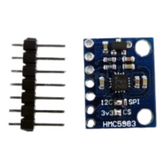
Getting Started with 7Semi BNO055 Sensor Module
Summary
Building robotics projects that require precise motion tracking can feel like navigating through a maze of complex sensors and confusing technical specifications.
Projects like self-balancing robots, a drone stabilization system, or an augmented reality application require accurate orientation for it to operate properly.
The challenge lies in finding a sensor that not only provides reliable data but also simplifies the integration process without requiring extensive calibration procedures.
The 7Semi BNO055 Sensor Module combines multiple motion sensors with intelligent onboard processing.
This comprehensive guide will walk you through everything you need to know about the 7Semi BNO055 sensor module, from its key features to practical implementation with Arduino.
By the end of this blog post, you'll have the knowledge and confidence to integrate this powerful bno055 sensor into your next project.
What is the 7Semi BNO055 Sensor Module?
The 7Semi BNO055 is an intelligent 9-axis absolute orientation sensor that is used to detect motion sensing in electronics projects.
Unlike traditional sensors that require external processing, this bno055 module combines three essential sensors - accelerometer, gyroscope, and magnetometer - with a built-in 32-bit ARM Cortex-M0+ microcontroller running sophisticated sensor fusion algorithms.
What makes this bno055 breakout board truly special is its ability to provide ready-to-use orientation data without the headache of complex mathematical calculations.
The sensor handles all the heavy lifting internally, delivering accurate quaternion, Euler angles, and linear acceleration data through a simple I2C interface.
This means you can focus on building your project rather than having to deal with complex mathematics.
The 7Semi version offers excellent value for money while maintaining the same high-quality performance standards as more expensive alternatives.
It's designed to work seamlessly with popular development platforms like Arduino, Raspberry Pi, and ESP32, which makes it an ideal choice for both beginners and experienced developers.
Key Features of BNO055 sensor module
The BNO055 sensor module comes packed with impressive features that set it apart from conventional motion sensors:
- Advanced Sensor Fusion: The built-in ARM Cortex-M0+ processor runs Bosch's proprietary sensor fusion algorithm, eliminating the need for external computation. This results in more accurate and stable orientation data compared to raw sensor readings.
- Multiple Output Formats: The sensor provides data in various formats including quaternions, Euler angles, rotation vectors, and linear acceleration, giving you flexibility in how you use the information.
- Wide Operating Voltage: It is compatible with both 3.3V and 5V systems, the sensor works with virtually any microcontroller platform without requiring level shifters.
- Intelligent Calibration: The bno055 calibration process is largely automated, with the sensor continuously calibrating itself during operation. This reduces setup time and improves long-term accuracy.
- Low Power Consumption: It is designed for battery-powered applications, the sensor offers multiple power modes to optimize energy usage based on your project requirements.
- Robust Communication: It supports both I2C and UART communication protocols, with the 7Semi version featuring convenient Qwiic connectors for easy daisy-chaining with other sensors.
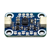
7Semi BNO055 Sensor Module Pinout

Understanding the bno055 pinout is essential for proper integration into your projects. The 7Semi breakout board simplifies connections with clearly labeled pins and additional features. Here's a detailed description of each pin and its function:
Power Supply Pins
VIN (Pin 1): The VIN pin serves as the main power input for the bno055 module and accepts a wide voltage range from 3.3V to 5V.
This flexibility makes the sensor compatible with both 3.3V and 5V microcontroller systems without requiring additional voltage level converters.
The onboard voltage regulator ensures stable 3.3V operation for the sensor regardless of the input voltage level.
3V3 (Pin 2): This pin provides a regulated 3.3V output that can be used to power other 3.3V components in your circuit.
The 3V3 output is generated by the onboard voltage regulator and can supply up to 150mA of current, making it suitable for powering additional sensors or small peripherals in your project.
GND (Pin 3): The ground pin establishes the common reference point for all electrical connections in your circuit.
This pin must be connected to the ground rail of your microcontroller or power supply to complete the electrical circuit and ensure proper operation of the bno055 sensor.
I2C Communication Pins
SDA (Pin 4): The Serial Data line is the bidirectional data communication pin for I2C protocol.
This pin carries all data transfers between the microcontroller and the bno055 breakout board, including sensor readings, configuration commands, and status information.
The SDA line requires a pull-up resistor to VCC, which is already included on the breakout board.
SCL (Pin 5): The Serial Clock line provides the timing reference for I2C communication. This pin carries the clock signal generated by the master device (typically your microcontroller) to synchronize data transfers with the bno055 module.
Like the SDA line, the SCL pin also has an onboard pull-up resistor for proper I2C operation.
Control and Status Pins
RST (Pin 6): The Reset pin provides hardware reset functionality for the bno055 sensor. When this pin is pulled low (connected to ground), it forces the sensor to restart and reinitialize all internal systems.
This pin is active-low, meaning it triggers a reset when connected to ground, and it includes an internal pull-up resistor so it can be left unconnected for normal operation.
ADD (Pin 7): The Address Selection pin allows you to change the I2C address of the bno055 module when multiple sensors are used on the same I2C bus.
By default, the sensor uses address 0x28, but connecting this pin to VCC changes the address to 0x29, enabling you to use two BNO055 sensors simultaneously without address conflicts.
INT (Pin 8): The Interrupt pin serves as an output that can signal various events and conditions to your microcontroller.
The bno055 sensor can generate interrupts for events such as motion detection, orientation changes, or when new sensor data becomes available.
This pin is particularly useful for creating responsive applications that need to react quickly to sensor events.
Protocol Selection Pins
PS0 (Pin 9): Protocol Selection pin 0 is used in conjunction with PS1 to configure the communication protocol for the bno055 module.
When both PS0 and PS1 are connected to ground (default configuration), the sensor operates in I2C mode. Different combinations of PS0 and PS1 states can select UART or HID-I2C communication modes.
PS1 (Pin 10): Protocol Selection pin 1 works together with PS0 to determine the communication interface.
In the default I2C configuration used by most Arduino projects, this pin should be connected to ground.
The PS1 pin allows advanced users to switch between different communication protocols based on their specific project requirements.
BNO055 vs MPU9250 Comparison
When choosing between motion sensors, the bno055 vs MPU9250 comparison often comes up. Here's a detailed comparison to help you make an informed decision:
| Feature | BNO055 | MPU9250 |
|---|---|---|
| Sensor Fusion | Built-in ARM processor with proprietary algorithm | Requires external processing |
| Calibration | Automatic continuous calibration | Manual calibration required |
| Data Output | Quaternions, Euler angles, linear acceleration | Raw sensor data only |
| Setup Complexity | Plug-and-play operation | Requires complex programming |
| Accuracy | High accuracy with stable output | Good accuracy but requires tuning |
| Power Consumption | Moderate (sensor fusion processing) | Lower (raw data only) |
| Cost | Higher initial cost | Lower initial cost |
| Development Time | Significantly faster | Longer development cycle |
| Availability | Good availability | Prone to counterfeits |
How to Connect 7Semi BNO055 to Arduino
Connecting the BNO055 to Arduino is straightforward thanks to the bno055 arduino library and simple I2C interface. Follow these steps for a successful connection:
Circuit Diagram

- Power Connection: Connect VIN to Arduino's 5V (or 3.3V) and GND to Arduino's ground
- I2C Communication: Connect SDA to Arduino's A4 pin and SCL to Arduino's A5 pin (for Uno/Nano)
- Optional Connections: RST and INT pins can be left unconnected for basic operation
Software Setup
First, install the required libraries through the Arduino IDE Library Manager:
- Adafruit BNO055 Library
- Adafruit Unified Sensor Library
Arduino Code Example
Here's a complete example to get you started with bno055 projects:
#include
#include
#include

// Create BNO055 object
Adafruit_BNO055 bno = Adafruit_BNO055(55, 0x28);

void setup() {
  Serial.begin(9600);
  Serial.println("BNO055 Orientation Sensor Test");

  // Initialize the sensor
  if (!bno.begin()) {
    Serial.println("No BNO055 detected. Check wiring!");
    while (1);
  }

  delay(1000);

  // Use external crystal for better accuracy
  bno.setExtCrystalUse(true);

  Serial.println("BNO055 initialized successfully!");
}

void loop() {
  // Get orientation data as Euler angles
  sensors_event_t orientationData;
  bno.getEvent(&orientationData, Adafruit_BNO055::VECTOR_EULER);

  // Display the data
  Serial.print("Heading: ");
  Serial.print(orientationData.orientation.x);
  Serial.print(" degrees");

  Serial.print(" | Roll: ");
  Serial.print(orientationData.orientation.y);
  Serial.print(" degrees");

  Serial.print(" | Pitch: ");
  Serial.print(orientationData.orientation.z);
  Serial.println(" degrees");

  // Check calibration status
  uint8_t system, gyro, accel, mag;
  bno.getCalibration(&system, &gyro, &accel, &mag);

  Serial.print("Calibration - Sys:");
  Serial.print(system);
  Serial.print(" Gyro:");
  Serial.print(gyro);
  Serial.print(" Accel:");
  Serial.print(accel);
  Serial.print(" Mag:");
  Serial.println(mag);

  delay(100);
}
This code demonstrates basic orientation reading and calibration status monitoring. The bno055 calibration values range from 0 (uncalibrated) to 3 (fully calibrated).
Calibration Tips
For optimal performance, follow these bno055 calibration guidelines:
- Gyroscope: Keep the sensor stationary for a few seconds
- Accelerometer: Place the sensor in six different orientations (all faces of an imaginary cube)
- Magnetometer: Move the sensor in a figure-8 pattern away from magnetic interference
Advanced Applications and Project Ideas
The versatility of the BNO055 opens up numerous possibilities for creative bno055 projects:
- Use the sensor for robot balance control, autonomous navigation, and gesture recognition systems.
- Create immersive controllers for virtual reality applications or motion-controlled games.
- Implement precise attitude control for quadcopters and other aerial vehicles.
- Develop fitness trackers, smart watches, or health monitoring devices that track user movement and orientation.
Conclusion
The 7Semi BNO055 sensor module represents a significant leap forward in motion sensing technology, offering professional-grade performance in an accessible package.
Its combination of multiple sensors, intelligent processing, and automatic calibration makes it an ideal choice for both beginners taking their first steps into motion sensing and experienced developers working on complex projects.
This sensor module offers exceptional value for makers and engineers looking to incorporate advanced motion sensing capabilities into their projects.
With its proven track record and excellent community support, this sensor will help transform your innovative concepts into reality.


