Tips to Use a Multimeter Like a Pro: Ultimate Guide for Makers
Summary
A multimeter is one of the most essential tools in any maker's toolkit. Whether you're troubleshooting a broken circuit, testing a battery, or verifying connections in your latest project, this versatile device does the heavy lifting for you.
But like any tool, using it effectively takes practice and knowledge. In this guide, we'll walk you through everything you need to know to master your multimeter and diagnose electrical problems like a professional. By the end, you'll feel confident tackling any measurement challenge that comes your way.

What Is a Multimeter and How Does It Work
A multimeter is an electronic instrument designed to measure multiple electrical properties in a single device. It’s the Swiss Army knife for electronics. It combines several measurement capabilities into one handheld unit.
The core function of any multimeter is to measure voltage, current, and resistance, but many modern models offer additional features like capacitance testing, frequency measurement, and temperature readings.
The fundamental principle behind a multimeter is relatively straightforward. The device contains a sensitive meter (either analog or digital) that displays measurements based on electrical signals flowing through internal circuits.
When you connect the multimeter's probes to a circuit, you're essentially creating a pathway for electrical current to flow through the device's measurement circuitry. The multimeter then interprets this current and converts it into a readable value on its display.
Most multimeters work by using precision resistors and operational amplifiers to convert the measured electrical quantity into a voltage that the display can show. This allows a single device to measure radically different electrical properties with just a few adjustments to its internal configuration.
Common Types of Multimeters
Understanding the differences between multimeter types helps you choose the right tool for your needs and use it effectively.
Digital Multimeters

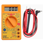
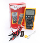
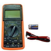
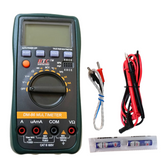
Digital multimeters are the modern standard and the most popular choice for makers today. They display measurements on an LCD or LED screen, making readings incredibly easy to interpret.
Digital models typically offer better accuracy, autoranging capabilities, and built-in safety features. They're also more affordable than they used to be, making them accessible for beginners and professionals alike.
Analog Multimeters

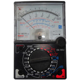
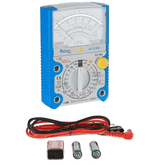
Analog multimeters use a needle that moves across a calibrated scale to show measurements. While they're less common now, many experienced technicians still appreciate them. Analog models excel at showing trends and changes in real-time—you can watch the needle move as you adjust circuits. However, they require more skill to read accurately and are generally less precise than digital versions.
Autoranging vs. Manual Selection
The distinction between autoranging and manual multimeters is important for practical usage. Autoranging multimeters automatically select the appropriate measurement scale, which is convenient and reduces errors from incorrect settings.
Manual multimeters require you to choose the correct range yourself, which takes more experience but gives you greater control and can be helpful when you need specific precision levels.
How to Measure Voltage, Current, and Resistance with Multimeters
These three measurements form the foundation of electrical diagnostics. Mastering them is essential for any maker.
Measuring Voltage
Checking voltage is often the first measurement you'll make. Voltage measures the electrical potential difference between two points in a circuit.
- Set your multimeter to the voltage mode (look for a V symbol)
- Determine whether you're measuring DC or AC voltage and select the appropriate setting
- For DC circuits (batteries, Arduino boards), use the DC voltage setting
- For AC circuits (wall outlets, power supplies), use the AC voltage setting
- Connect the red probe to the positive point and the black probe to the ground or negative point
- Read the value displayed on your screen
- When using a multimeter to test batteries, measure across the battery terminals to verify its current voltage output
Measuring Current
Current measurement tells you how much electrical charge is flowing through a circuit.
- Switch your multimeter to the current mode (marked with an A for amperes)
- Decide between DC and AC current based on your circuit type
- This is crucial: current measurement requires breaking the circuit and inserting your multimeter in series
- Connect the multimeter between two components so current flows through the device
- The red probe connects to the positive side of the break, the black to the ground side
- Read the amperage displayed
- Be cautious with current measurements—inserting a multimeter incorrectly can damage both the device and your circuit
Measuring Resistance
Resistance shows how much a component opposes electrical flow, measured in ohms.
- Set your multimeter to the resistance mode (Ω symbol)
- Always measure resistance with the circuit powered off
- Connect the probes across the component you're testing
- The polarity doesn't matter for resistance measurements
- Measure current and resistance with a multimeter by ensuring your circuit is de-energized before attempting resistance checks
- Read the ohm value on the display
Checking Continuity and Diodes with a Multimeter
Beyond basic measurements, multimeters offer specialized testing capabilities that prove invaluable in troubleshooting.
Continuity Testing

Continuity testing determines whether a complete path exists for electricity to flow. This is essential when you're unsure if a wire is broken or a connection is intact.
- Locate the continuity mode on your multimeter (usually marked with a sound wave symbol or labeled "Continuity")
- Power off your circuit completely
- Place one probe on each end of the path you're testing
- If continuity exists, the multimeter beeps and displays zero or very low resistance
- If there's a break in the path, you'll hear no beep and see infinite or very high resistance
- Use continuity and diode testing to verify solder joints, trace wire breaks, and confirm connections before powering your project
Diode Testing
Many multimeters include a dedicated diode testing mode that measures the forward voltage drop across a diode.
- Switch to diode mode (usually marked with a diode symbol)
- Place the red probe on the positive (anode) side and black on the negative (cathode) side
- A good diode displays a voltage drop between 0.4 and 0.7 volts
- Reverse the probe positions; a functional diode shows infinite resistance in this direction
- If you get continuity in both directions or neither direction, the diode is faulty
How to Test Electronic Components Safely
Safety should always be your priority when working with electrical circuits and testing equipment.
Understanding Voltage Safety
Different voltage levels present different hazards. Household AC voltage (120V or 240V depending on your region) can be lethal, while low-voltage DC circuits (5V or 12V) are generally safe to handle. Always respect the circuit's voltage level before testing.
Proper Probe Usage
Your multimeter's multimeter probes are the interface between your device and the circuit. Handle them with care:
- Inspect probes regularly for damage, cracks, or exposed metal
- Ensure probes are firmly inserted into the correct jacks on your multimeter
- Use appropriate probe tips for your application (standard points, alligator clips, or specialty probes)
- Keep probes away from moisture and corrosive environments
- If you need to know how to replace or calibrate multimeter probes, consult your device's manual for model-specific instructions
Testing Safely
- Always start with the highest measurement range to avoid overloading your multimeter
- Never measure voltage with the circuit powered down unless specifically testing for residual charge
- When testing sensors and components with a multimeter, ensure you understand the component's specifications first
- Keep one hand in your pocket when testing high-voltage circuits to prevent current from passing through your chest
- Test on known-good circuits first to verify your technique before diagnosing problem circuits
Pro Tips to Get Accurate Readings Every Time
Accuracy separates amateurs from professionals. These practical techniques will improve your results significantly.
Stabilize Your Measurements
Electrical readings can fluctuate, especially in circuits with varying loads. Allow a few seconds after connecting your probes before reading the value. This gives the circuit time to stabilize and the multimeter's circuitry to settle.
Use Proper Multimeter Settings and Range Selection
On manual multimeters, selecting the correct range is critical. Start with a higher range than you expect, then work downward to a more precise setting. This protects your multimeter from damage and gives you better accuracy.
With autoranging models, you still benefit from understanding what measurement you expect, allowing you to spot unrealistic readings immediately.
Minimize Environmental Interference
- Perform measurements away from strong electromagnetic fields and high-power equipment
- Keep multimeter leads away from power cables and high-current circuits
- Avoid testing in extremely hot or cold environments, as temperature affects accuracy
- Allow your multimeter to warm up for a few minutes before critical measurements
Reference Known Values
Before trusting your multimeter's readings on problem circuits, verify it works correctly on known-good components. Test a battery you know is fresh, check a resistor with a color code you've verified, or measure a power supply you trust. This reference point confirms your multimeter is functioning properly.
Read multimeter guide display Carefully
- Check which units the display is showing (millivolts, volts, kiloohms, ohms)
- Look for decimal point placement, especially on analog meters
- Verify you're reading the correct scale if your multimeter shows multiple ranges
- Note any warning symbols or indicators the display provides
Common Mistakes Beginners Should Avoid
Learning from others' mistakes accelerates your mastery.
- Ignoring polarity on DC measurements: Reversing probes on voltage tests gives negative readings. Always connect red to positive and black to ground or negative.
- Measuring current with incorrect probe placement: Inserting a multimeter in parallel for current measurements (instead of series) can damage the device and circuit. Break the circuit and insert the multimeter in the current path.
- Forgetting to power off before resistance testing: Measuring resistance on a live circuit gives useless readings and can damage your multimeter's sensitive input circuits.
- Using DC settings for AC circuits: The scales are different. Measuring AC voltage on a DC setting shows incorrect readings that might lead you to wrong conclusions.
- Leaving probes on the wrong terminals: Accidentally measuring current on the voltage input jacks can destroy your multimeter's internal circuitry instantly.
- Trusting a multimeter without verification: Even new multimeters can have manufacturing defects. Always verify basic functionality on known-good components first.
Conclusion
Mastering how to use your multimeter transforms you from someone who can follow instructions into someone who truly understands their circuits. This combination of knowledge and practice.
Understanding what each measurement means, knowing which settings to use, and developing habits that prioritize accuracy and safety, separates confident makers from frustrated beginners. Start with the basics, practice on simple projects, and gradually tackle more complex diagnostics.
Soon, reaching for your multimeter will feel as natural as reaching for a screwdriver, and you'll find yourself troubleshooting problems that would have stumped you before. The multimeter is your gateway to deeper electrical understanding and more successful projects.


