How to Test a Diode Using Analog and Digital Multimeters
Summary
If you’ve ever looked inside an electronic device, you’ve seen a complex cityscape of tiny components, each with a specific job. Among these, the humble diode is one of the most fundamental.
Think of it as a one-way street for electricity; it lets current flow in one direction but blocks it from going the other way. This simple but crucial function makes diodes essential in everything from phone chargers to car alternators.
But what happens when one of these electronic gatekeepers stops working correctly? A single faulty diode can bring an entire circuit to a halt. Fortunately, you don't need a high-tech lab to diagnose a bad diode.
With a common tool called a multimeter, you can quickly determine if a diode is healthy or if it's the source of your electronic troubles.
Whether you have a modern digital multimeter or a classic analog one, this guide will walk you through the process step-by-step.
Learning this skill is like a mechanic learning to check a fuse—it's a basic diagnostic that can save you hours of frustration and help you repair your own devices with confidence.

What Is a Diode and Its Symbol in Circuits?
Before you can test the diode, it’s helpful to understand what it is and how to identify it. A diode is a semiconductor component with two terminals: an anode (the positive side) and a cathode (the negative side).
Its primary job is to control the direction of current flow. When current flows from the anode to the cathode, the diode allows it to pass easily.
This is called being forward-biased. However, if the current tries to flow from the cathode to the anode, the diode blocks it almost completely. This state is known as reverse biased.
This one-way property is what allows diodes to convert alternating current (AC), which constantly changes direction, into direct current (DC), which flows in a single direction. This process, called rectification, is fundamental to powering most electronic devices.
Identifying a diode is straightforward once you know what to look for.
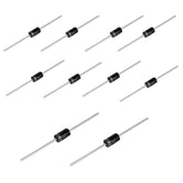
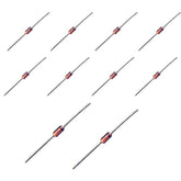
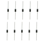
- Physical Appearance: On the body of a typical cylindrical diode, the cathode is almost always marked with a colored band, usually black or silver. The other end, without the band, is the anode.

- Circuit Diagram: The Diode symbol and orientation in a circuit diagram looks like an arrow pointing at a vertical line. The arrow represents the anode and points in the direction of conventional current flow, while the vertical line represents the cathode.

Knowing the Diode polarity test—that is, correctly identifying the anode and cathode—is the first and most critical step in performing a successful Diode Test.
How to Test a Diode Using a Digital Multimeter
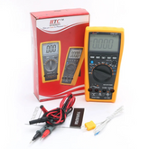
Digital multimeters are the most common tool for testing electronic components today, and they make the process incredibly simple.
Digital Multimeter offer two primary methods to test a diode: Diode Test mode and Resistance mode (Ω). The Diode Test mode is almost always the better choice.
Using the Diode Test Mode
The diode check function is designed specifically for this task. In this mode, the multimeter sends a small current through the diode and measures the voltage drop across it. This voltage drop tells you if the junction inside the diode is working correctly.
Here is the standard Diode Test procedure using this function:
- Ensure Safety: Before you begin, disconnect all power to the circuit. If the circuit has large capacitors, make sure they are fully discharged. You can check for any residual voltage with your multimeter's voltage setting.
- Isolate the Diode: For the most accurate reading, it's best to desolder and remove one end of the diode from the circuit board. This prevents other components in the circuit from interfering with the measurement and giving you a false reading.
- Set Up the Multimeter: Turn the rotary dial on your multimeter to the Diode Test mode. This setting is usually marked with the diode symbol (the arrow pointing at a line).
- Perform the Forward-Bias Test: Connect the multimeter's red probe to the diode's anode and the black probe to its cathode (the end with the band). This configuration attempts to pass current in the forward direction. A good silicon diode will show a voltage drop reading between 0.5 and 0.8 volts. For germanium diodes, this reading is typically lower, around 0.2 to 0.3 volts. This reading indicates the diode is conducting as expected.
- Perform the Reverse-Bias Test: Now, reverse the connections. Place the black probe on the anode and the red probe on the cathode. A good diode will block the current flow. Your multimeter should display "OL" (Over Limit) or "I" (Infinity). This OL reading indicates that the resistance is too high to measure, meaning the diode is correctly blocking the current.
Using the Resistance Mode (Ω)
If your digital multimeter doesn't have a dedicated Diode Test mode, you can still test a diode using the resistance setting (marked with the omega symbol, Ω). This method is less definitive but can still provide useful information.
- Follow the same safety and isolation steps as above (disconnect power, remove the diode from the circuit).
- Set the multimeter dial to the Resistance mode (Ω). You may need to select a range, such as 2kΩ or 20kΩ.
- To measure the forward-biased resistance, connect the red probe to the anode and the black probe to the cathode. A good diode should show a relatively low resistance reading. The exact value isn't as important as the difference between the forward and reverse readings.
- To measure the reverse-biased resistance, switch the probes. A good diode should now show a very high resistance, often displayed as "OL" on the multimeter's screen.
The key is to see a significant difference: low resistance in one direction and very high resistance in the other.
How to Test a Diode Using an Analog Multimeter
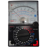
The process of Diode testing with multimeter is a bit different with an analog, or needle-based meter, but it relies on the same principle of checking resistance.
A critical point to remember is that on many analog multimeters, the polarity of the probes is reversed when in resistance mode. The black probe is actually positive, and the red probe is negative.
This is because the meter uses an internal battery to send a current out through the probes to measure resistance. Always check your multimeter's manual if you're unsure.
Here’s how to test a diode with an analog multimeter:
- Set the Meter: Turn the dial to a low-resistance setting, like "R x 10" or "R x 100". Touch the probes together and use the "Zero Adjust" knob to calibrate the needle to the zero-ohm mark on the right side of the scale.
- Forward-Bias Test: Assuming the polarity is reversed, connect the black probe to the anode and the red probe to the cathode. For a good diode, you should see the needle sweep to the right, indicating a low resistance.
- Reverse-Bias Test: Now, swap the probes (red to anode, black to cathode). The needle should barely move, staying on the far-left side of the scale. This indicates a very high, near-infinite resistance.
With an analog meter, a good diode shows low resistance one way and high resistance the other.
Forward-Biased vs Reverse-Biased Diode Readings
To summarize, the health of a diode is determined by comparing its behavior in both forward and reverse-biased conditions. A healthy diode should act like a closed switch in one direction and an open switch in the other.
| Test Method | Good Diode - Forward Bias | Good Diode - Reverse Bias |
|---|---|---|
| Digital Meter (Diode Test) | Shows a voltage drop (e.g., 0.5V - 0.8V) | Shows "OL" or "I" (infinite) |
| Digital Meter (Resistance) | Shows a relatively low resistance value | Shows "OL" or "I" (infinite) |
| Analog Meter (Resistance) | Shows low resistance (needle moves right) | Shows high resistance (needle stays left) |
Tips to Identify a Faulty Diode in a Circuit
When a diode fails, it typically does so in one of three ways: open, shorted, or leaky. Your multimeter readings will clearly point to which of these failures has occurred.
- Open Diode: An open diode is like a permanently open drawbridge; it doesn't allow current to flow in either direction.
- Test Result: When you test the diode, your multimeter will show "OL" (or infinite resistance) in both the forward and reverse bias tests. The diode is effectively broken and acts like a gap in the circuit.
- Shorted Diode: A shorted diode is the opposite; it's like a bridge that's permanently stuck down, allowing traffic to flow freely in both directions.
- Test Result: The diode will show a very low voltage drop (often near 0V or 0.4V) or a very low resistance reading in both the forward and reverse directions. It has lost its one-way-gate functionality completely.
- Leaky Diode: This is a more subtle failure. A leaky diode works, but not perfectly. It blocks most of the reverse current but allows a small amount to "leak" through.
- Test Result: In the forward-bias test, it may show a normal reading. However, in the reverse-bias test, instead of showing "OL," it will display a very high but measurable resistance or voltage value.
Remember, for the most reliable diagnosis, always try to test the diode out of the circuit. In-circuit testing can be misleading because the current from your multimeter can travel through other paths, making a bad diode appear good or vice versa.
Conclusion
Mastering the Diode Test is a fundamental skill that empowers anyone working with electronics. It transforms troubleshooting from a guessing game into a methodical process.
By understanding how a diode should behave and how to use a multimeter to check its function, you can quickly pinpoint the cause of a circuit failure.
Whether you're a hobbyist fixing a guitar pedal, a student learning the basics of circuits, or a technician repairing a power supply, this simple procedure is an invaluable tool in your diagnostic arsenal.
The next time a device fails, grab your multimeter, and you’ll be one step closer to bringing it back to life


