How to use a digital multimeter
Summary
Unlock the full potential of your digital multimeter with our easy-to-follow guide. Start with an introduction to what a digital multimeter is and its various uses. Learn the essential steps to prepare your multimeter for use, ensuring accurate measurements. Discover additional functions and tests that expand your multimeter's capabilities, from measuring voltage and current to checking continuity and resistance. Perfect for beginners and experienced users, this guide will enhance your electronic troubleshooting and diagnostic skills. Click now to master your digital multimeter!
INTRODUCTION:
A digital multimeter (DMM) is a Powerful and essential instrument for both professionals and consumers who works with electrical circuits. The multifunctional device combines many measurement capabilities into a single instrument, allowing for more precise measurement of voltage, current, and resistance.
Individuals in areas such as electricians and do-it-yourself enthusiasts benefit from mastering the use of a digital multimeter since it streamlines work, improves efficiency, and reduces potential errors that could result in significant costs. The study of digital multimeters goes thoroughly into not only their basic parts and functionalities, but also the critical preparation actions required for their proper use.

This comprehensive review goes on to provide specific guidance on how to accurately measure voltage, resistance, and current, incorporating a fundamental understanding of electrical parameters. Furthermore, the discussion on digital multimeters dives into a study of the additional features and tests that considerably boost their utility, serving to raise the tool beyond its fundamental tasks and catering to varied sophisticated testing needs.
DIGITAL MULTIMETER:
The digital multimeter, a versatile instrument prized by engineers, technicians, and enthusiasts for its numerous purposes, is essential for the rigorous investigation, diagnosis, and resolution of problems inside electrical circuits, components, and devices with extraordinary precision and speed.
Since the groundbreaking debut of the first digital multimeter in the late 1970s, the landscape of electrical measurements has undergone a remarkable transformation, putting an end to the limitations of analog meters reliant on needles and leading to in a new era defined by cutting-edge technology known for its impeccable accuracy and unwavering dependability across a wide range of applications.

Key Components:
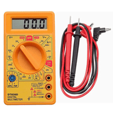
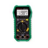
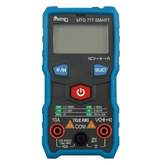
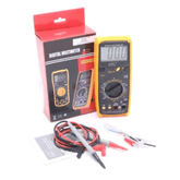
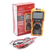
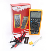
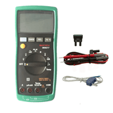
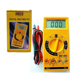
- Display: The multimeter's display panel is essential for displaying measured readings in a clear numerical manner. Furthermore, some advanced models improve the user experience by offering graphical representations of data, making it easier to interpret and analyze the displayed measures.
- Selection Knob: The selection knob is critical, allowing users to readily choose the sort of measurement they require. This adaptable dial allows for quick change between multiple modes, such as voltage, current, and resistance, resulting in precise and efficient readings based on the user's demands.
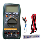
- Input Jack: These are the ports where you can connect your test leads. Common jacks are: COM (common ground), VΩ (voltage and resistance), and A (current).
- Test Leads: Test leads are crucial components of a multimeter, and are frequently made up of red and black probes that represent positive and negative connections, respectively. These strong and insulated leads are used to establish a reliable electrical connection between the multimeter and the circuit under test. Users can use the test leads to measure a variety of electrical parameters in a safe and accurate manner, allowing for full circuit testing and analysis for optimal functionality and performance.
PREPARING TO USE THE DIGITAL MULTIMETER:
Prioritize the Safety
- Read the manual carefully Before using the Digital Multimeter read the manual carefully, this helps us to understand the functionality and precautions.
- Check the Multimeter Check if any physical damage have been there in the multimeter. Ensure that the multimeter is working fine.
- Use Protective Gear Wear Appropriate equipments like gloves, safety glasses especially when working with high voltage.
Setting up the Multimeter

- Turn off the circuit: Turn off the circuit when not in use which avoids the risk of electric shock.
- Select the Proper Function: Use the Selection Knob to choose the measurement function wisely.
- Connect the test Leads Connect the black wire to the COM jack and the red lead to the appropriate jack for your measurement (VΩ for voltage and resistance, A for current).
Measure the voltage
When measuring voltage, it is important to understand whether you are working with AC or DC. This distinction is critical in electrical engineering and has numerous applications.
AC voltage, defined by its continuous change in direction, is extensively used in domestic outlets to safely power a variety of appliances and devices. DC voltage, on the other hand, is well-known for its steady flow in a single direction and frequently linked with battery backup and electrical device operation.
Steps:
- Set the function Select the selection knob to the appropriate voltage setting.
- Select the Range If some cases will be there that the multimeter is not auto-ranging then select the Range.
- Connect the Test Leads: Connect the Black Lead to the COM port and the red to the VΩ.
- Measure the voltage: Place the black probe on the negative terminal which is ground and the red probe to the positive terminal of the component.
Measuring Resistance
Understanding Resistance is a measure of how much a component or material resists the flow of electrical current. It is measured in Ohms (Ω).
Resistance testing is important for determining the integrity of electrical components and connections.

Steps:
- Set the Function Select the resistance setting (Ω).
- Disconnect power: To avoid damaging the multimeter, ensure that the circuit is entirely turned off.
- Connect the test leads Connect the black and red leads to the COM and VΩ ports, respectively.
- Measuring Resistance: Place the probes across the component or area of the circuit you want to test. The resistance value can be read from the display.
Measuring Current:
AC Versus DC Current, like voltage, can be alternating current or direct current. AC current alternates direction, whereas DC current travels in a single direction.
Steps:
- Set the Function Select the proper current setting (A- for DC current and A~ for AC current).
- Select the Range If your multimeter doesn't auto-range, choose a range that is more than the projected current.
- Connect the test leads Connect the black lead to the COM port and the red lead to the A port (or mA port for lower current).
- Break the circuit. Unlike voltage and resistance measurements, measuring current requires you to break the circuit and connect the multimeter to the load.
ADDITIONAL FUNCTIONS AND TESTS:
Continuity Test:
A continuity test checks if there is a complete path for current to flow. It is useful for verifying connections and identifying broken wires.
- Set the Function: Turn the selection knob to the continuity test setting, usually indicated by a diode symbol or sound wave symbol.
- Connect the Test Leads: Connect the black lead to the COM port and the red lead to the VΩ port.
- Test Continuity: Place the probes on either end of the component or wire. If there is continuity, the multimeter will beep.
The Diode Test
A diode test measures a diode's forward voltage drop to ensure that it is working.

- Set the Function :Turn the selection. Connect the test leads: the black lead to the COM port, and the red lead to the VΩ port.
- Examine the diode: Place the probes across the diode, with red on the anode and black on the cathode.
- Testing the Diode: Position the probes across the diode (red probe on the anode, black probe on the cathode). The forward voltage drop will appear on the display. Reverse the probes to see if a high value indicates that the diode is not conducting in the opposite direction.
Capacitance Measurements
Some digital multimeters can measure capacitance, or a component's ability to store an electric charge.
- Set the Function: Turn the selection knob to the capacitance position (F).
- Discharge the Capacitor: To avoid damaging the multimeter, ensure that the capacitor is totally depleted.
- Connect the test leads: Insert the black lead into the COM port and the red lead into the VΩ port.
- Assess Capacitance: Place the probes on the capacitor terminals. The capacitance value will appear on the display.
Frequency measuring.
Frequency measurements are useful for establishing the frequency of alternating current signals.
- Set the Function: Turn the selection knob to the desired frequency (Hz).
- Connect the Test Leads: Plug the black and red leads into the COM and VΩ ports, respectively.
- Measure Frequency: Place the probes against the signal source. Frequency will be displayed.
CONCLUSION:
A digital multimeter is a very useful and vital instrument for anyone working with electrical circuits. By delving thoroughly into its different capabilities and mastering the art of its proper application, you open up a world of possibilities for performing a wide range of measurements properly and, more importantly, safely. It is vital that you always put safety above all else, meticulously following the safety regulations provided and thoroughly familiarizing yourself with the manufacturer's paperwork to ensure maximum efficacy and security in any measurement work you undertake.
It is strongly advised that you start with the fundamentals, progressively improving your skills by practicing with your multimeter on simple circuits before progressing to more elaborate and advanced tasks. Through constant practice, you will progressively create a firm foundation of knowledge and competence, allowing you to approach increasingly complicated electrical tasks with confidence and the precision.
Digital multimeters having the ability to successfully diagnose and troubleshoot a wide variety of electrical problems. This road of mastery will not only increase your technical competency, but will also boost your confidence, allowing you to tackle any electrical problem with confidence and poise, knowing that you have the skills and knowledge to deal with it head on.


