Interface a Flex Sensor with Arduino: Step-by-Step Guide
Summary
Bending and flexing are everyday movements we don't often think about but capturing them digitally opens doors to innovative applications. Understanding how to measure bending is essential for people working on wearable gloves, gesture-controlled devices, or interactive game controllers.
A flex sensor combined with Arduino provides an affordable and straightforward solution for detecting and quantifying physical deflection, transforming mechanical motion into digital signals that your projects can respond to.

What are Flex Sensors?
Flex sensors are specialized electronic components that function as variable resistors, changing their electrical resistance in response to physical bending or flexing. Unlike traditional sensors that detect temperature, light, or distance, a flex sensor is specifically engineered to measure deflection along a single axis.
These sensors consist of a thin, flexible substrate with a conductive ink layer on the surface. When you bend the sensor, the conductive material stretches, causing its resistance to increase proportionally to the degree of bending.

The construction of a flex sensor makes it ideal for applications requiring physical interaction:
- Slim, lightweight design allows integration into flexible materials
- Durable conductive ink withstands repeated bending cycles
- Simple two-terminal design for straightforward circuit integration
- Low-cost alternative to sophisticated motion capture systems
- Operating voltage ranges from 0V to 5V, making it compatible with microcontroller platforms
These sensors are commonly found in virtual reality applications, musical instruments, robotic limbs, and fitness trackers where bending detection provides intuitive user interaction.
How does a Flex Sensor Work
Understanding the operational principle of a bending sensor requires knowledge of basic electrical properties. At its core, a flex sensor operates on the principle that resistance changes with deformation.
When the sensor lies completely flat, its conductive ink maintains a nominal resistance of approximately 25 kilohms. This baseline value serves as the reference point for all measurements.
When you introduce bending into the sensor, something remarkable happens at the microscopic level:
- Flat Position: The conductive layer maintains nominal resistance around 25kΩ
- 45-Degree Bend: The conductive ink stretches, causing resistance to approximately double
- 90-Degree Bend: Maximum bending results in resistance reaching approximately 100kΩ or higher (up to 125kΩ depending on bend radius)
- Return to Flat: Resistance returns to original value as sensor straightens
The fundamental mechanism driving this behavior mirrors what happens when you stretch a rubber band—as the surface area becomes longer and thinner, its ability to conduct electricity diminishes, thus increasing resistance.
The resistance-based sensor design allows Arduino boards to measure this changing resistance using their analog input pins and convert it into usable data. This proportional relationship between bending angle and resistance forms the foundation for all applications using flex sensors.
Typical specifications you'll encounter include a resistance tolerance of ±30%, operating temperatures from -45°C to 80°C, and power ratings of 0.5 watts continuous or 1 watt peak. These specifications ensure reliable performance across various environmental conditions and project requirements.
Circuit Diagram to Connect Arduino with Flex Sensor

The attached circuit diagram illustrates the fundamental setup for connecting a flex sensor to Arduino. This is a voltage divider configuration, one of the most common approaches for interfacing a flex sensor with Arduino.
Key Components in the Diagram:
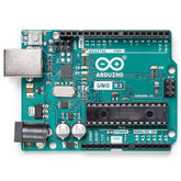
- Arduino UNO microcontroller unit
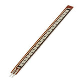
- Flex sensor (the reddish-brown vertical component)
- Fixed resistor (typically 10kΩ or similar value)
- Breadboard for prototyping
- Connecting wires (red and black) establishing the circuit path
How the Circuit Works:
The flex sensor and fixed resistor form a series connection between the Arduino's 5V power supply and ground. The analog input pin (typically A0) connects to the junction point between these two resistors.
As the flex sensor's resistance changes with bending, the voltage at this junction point also changes. The Arduino's analog-to-digital converter samples this voltage, providing a numerical value between 0 and 1023 that represents the sensor's current resistance state.
The red wire from the junction feeds the signal to the analog input, while the green wire completes the circuit path. This simple yet elegant configuration requires minimal components while providing accurate bending measurements.
How to Interface a Flex Sensor with Arduino: Step-by-Step Guide
Hardware Assembly
Step 1: Gather Your Components
Begin by collecting all necessary materials for your flex sensor connection with Arduino Uno project. You'll need an Arduino Uno microcontroller, one flex sensor (typically the FS-L-0055 model), a resistor (10kΩ works well as a voltage divider), jumper wires, a breadboard, and a USB cable for programming. Having a multimeter nearby helps verify connections during assembly.
Step 2: Prepare the Breadboard
Arrange your breadboard with clear power and ground rails. Position the flex sensor vertically on the breadboard, ensuring both terminals have good contact with separate rows.
This prevents accidental short circuits and keeps your assembly organized. Label or note the terminals mentally. You'll need to distinguish between the sensor's two connection points.
Step 3: Create the Voltage Divider Circuit
Connect the fixed resistor between the flex sensor's first terminal and the Arduino's ground rail. This creates your voltage divider configuration. Next, connect the flex sensor's first terminal to the Arduino's 5V power supply.
The flex sensor's second terminal connects to both the fixed resistor and the Arduino's analog input pin (A0). This junction point becomes your measurement node. Double-check all connections before proceeding to prevent damage.
Step 4: Verify Physical Connections
Test each connection by gently tugging on wires to ensure they're seated firmly. Use a multimeter to measure continuity along your circuit path if you have one available. Proper contact is crucial for consistent readings.
Software Programming
Step 5: Set Up Your Arduino IDE

Launch the Arduino Integrated Development Environment on your computer and connect your Arduino via USB cable. Select the appropriate board (Arduino/Genuino Uno) and COM port from the Tools menu. This establishes communication between your computer and the microcontroller.
Step 6: Write the Basic Sketch
Begin with fundamental code that reads and displays sensor values. Initialize your analog pin as input, establish serial communication at 9600 baud rates, and create a loop that continuously reads the analog value. The following approach demonstrates this process:
int flexPin = A0;
int ADCflex;

void setup() {
  Serial.begin(9600);
  pinMode(flexPin, INPUT);
}

void loop() {
  ADCflex = analogRead(flexPin);
  Serial.println(ADCflex);
  delay(500);
}
This foundation captures raw ADC values and transmits them to your serial monitor.
Step 7: Calculate Actual Resistance
Transform raw ADC values into meaningful resistance measurements using the voltage divider equation. When you connect flex sensor with Arduino, the analog value represents voltage, which you convert using the formula: Rflex = R_DIV × (VCC / Vflex - 1.0).
This mathematical transformation reveals the actual resistance your resistance-based sensor is exhibiting at any given moment.
Step 8: Convert Resistance to Bending Angle
Map the calculated resistance values to bending angles by establishing the relationship between your flat resistance baseline (around 25kΩ) and maximum bend resistance (around 125kΩ). Use the Arduino map() function to scale resistance values to degrees:
float angle = map(Rflex, 25000, 125000, 0, 90);
Serial.println("Bend: " + String(angle) + " degrees");
This conversion allows your project to interpret physical bending in human-readable angles.
Testing and Refinement
Step 9: Upload and Monitor
Compile your sketch and upload it to the Arduino. Open the Serial Monitor at 9600 baud rate and observe the real-time values as you bend and straighten your sensor.
You should see numbers increase as you apply bending force and decrease as you relax the sensor. Watch for smooth transitions rather than erratic jumping, which might indicate loose connections.
Step 10: Calibrate for Your Specific Sensor
Individual flex sensors exhibit slight variations due to manufacturing tolerances (±30% is typical). Record the ADC values when your sensor is completely flat and when bent to 90 degrees.
Use these calibrated values instead of theoretical numbers to improve accuracy in your angle calculations. This personalization ensures your particular flex sensor with Arduino setup provides reliable measurements.
Step 11: Integrate with Your Application
Once calibration is complete, add functionality that responds to bending values. This might include LED brightness control, servo motor positioning, game controller input, or data logging. The flexibility of Arduino programming allows countless creative applications for your flex sensor with Arduino integration.
Step 12: Troubleshooting Common Issues
If you encounter inconsistent readings, first verify all connections are secure. Check that your fixed resistor value hasn't changed (occasionally physical stress damages components).
Ensure you're reading from the correct analog pin. If values remain stuck at specific numbers, suspect a loose wire or poor breadboard contact. Reseating components usually resolves such issues.
Conclusion
Interfacing a flex sensor with Arduino opens fascinating possibilities for interactive projects and wearable applications. By understanding how bending sensors operate as resistance-based sensors and mastering the voltage divider circuit configuration, you've equipped yourself with knowledge applicable to numerous electronic designs.
The step-by-step approach presented here provides a scalable foundation, from simple bending detection to complex gesture recognition systems. Your Arduino, combined with flex sensor technology, enables you to bridge the physical and digital worlds, creating responsive devices that react intelligently to human movement and interaction.


