Build a Self-Balancing Robot with Arduino for Beginners
Summary
After years of diving into robotics projects and watching countless makers struggle with their first attempts at building dynamic systems, I can tell you that few projects are as rewarding, or as educational, as creating your own self-balancing robot.
When I first attempted this Arduino project several years ago, I was amazed by how this seemingly simple concept could teach so many fundamental engineering principles in one go.
The beauty of a self-balancing robot lies not just in its impressive ability to stay upright, but in how it demonstrates the elegant dance between sensors, microcontrollers, and motors working in perfect harmony.
In this comprehensive walkthrough, we'll build a two wheeled self balancing robot from the ground up using Arduino and commonly available components.
By the end of this tutorial, you'll have not only a functioning 2 wheel Arduino robot but also a deep understanding of the physics and programming concepts that make it all possible.

Overview of Self-balancing Robot Project
You know what's absolutely fascinating about self-balancing robots? They're basically doing something that seems impossible - staying upright on just two wheels while constantly fighting gravity.
I remember the first time I successfully got one working; I just sat there watching it wobble and correct itself, thinking "this little automated vehicle is literally defying physics right in front of me!" At its core, a self-balancing robot works exactly like you do when you're trying not to fall over. It's constantly making tiny adjustments to stay balanced.
The Physics Behind the Balance
The core challenge for any self-balancing robot is overcoming the instability of an inverted pendulum system. While a regular pendulum naturally hangs downward, our two wheeled self balancing robot is essentially an inverted pendulum that naturally wants to fall over. This creates an "unstable equilibrium" where the robot is balanced but any disturbance will cause it to topple without active correction.
Through testing different Arduino Project configurations, the key to successful balancing involves three critical measurements: the robot's current angle, its angular velocity (how fast the angle is changing), and the response time of motor corrections. The robot calculates its predicted position and adjusts wheel speeds preemptively - essentially anticipating its own movement.
The Control System at Work
This Arduino robot project demonstrates PID (Proportional-Integral-Derivative) control in action. The "P" component responds to current tilt, the "I" component addresses persistent lean over time, and the "D" component predicts future movement based on rate of change. Tuning these three parameters is often the most challenging aspect of building a self-balancing robot.
When the robot detects forward lean, it accelerates the wheels forward to reposition under the shifting centre of gravity. For backwards lean, the wheels decelerate or reverse to allow the weight to return over the wheel base. This process occurs dozens of times per second, creating the smooth balancing behaviour of a 2 wheel Arduino robot.
Sensor Integration and Real-time Processing
Successful self-balancing robot operation depends on accurate orientation measurement and rapid response times. Experience with various robot project using Arduino builds shows that sensor selection and control loop speed determine whether the robot maintains balance or falls.
Modern Arduino Project implementations typically use an IMU (Inertial Measurement Unit) combining accelerometer and gyroscope data. The accelerometer indicates gravitational direction (tilt angle), while the gyroscope measures rotational velocity. Sensor fusion techniques combine these data sources to provide orientation information that updates hundreds of times per second - sufficient for the automated vehicle to maintain balance even when disturbed.
List of Components needed

Now that you have an idea of the science behind how a self-balancing robot works, let's look at the components needed to build one. Building a self-balancing robot from scratch means gathering the right components from the start. Trust me, there's nothing more frustrating than being halfway through your Arduino Project and realizing you're missing a critical part.
I've refined this component list through multiple builds, learning which parts are absolutely essential and which ones you can substitute or skip entirely. The good news is that most of these components are readily available and won't break the bank, making this Arduino robot project accessible to makers at any budget level.
Essential Hardware Components
Microcontroller:
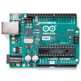
- Arduino Uno R3 or Arduino Nano (Arduino Uno recommended for beginners)
- USB cable for programming and power during development
Sensors:
- MPU6050 6-axis IMU (Gyroscope + Accelerometer) - the brain of your self-balancing robot
- Connecting wires (jumper wires, male-to-female and male-to-male)
Motor Control:
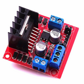
- L298N Motor Driver Module (handles the power and direction control for both motors)
- 2x Motor coupling connectors
Motors and Wheels:
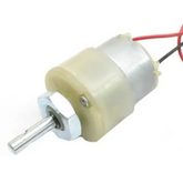
- 2x 6-12v DC Motors with Encoders
- 2x Wheels (diameter 65-70mm recommended for stability)
- Motor mounting brackets
Power System:
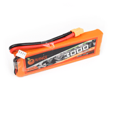
- 7.4V-11.1V Lithium Polymer (LiPo) battery pack (2S or 3S configuration)
- Battery connector and power switch
- Voltage regulator module (if using higher voltage batteries)
Structural Components
Frame and Mounting:
- Acrylic or aluminum chassis (can be laser-cut or purchased)
- M3 bolts and nuts (various lengths: 10mm, 15mm, 20mm)
- Spacers and standoffs for component mounting
- Double-sided foam tape for temporary component placement
Protection and Finishing:
- Heat shrink tubing for wire connections
- Cable ties for wire management
- Foam padding for crash protection (your two wheeled self balancing robot will fall during testing)
Tools Required
Basic Tools:
- Soldering iron and solder (for permanent connections)
- Wire strippers and cutters
- Screwdriver set
- Hot glue gun for quick fixes
Measurement Tools:
- Multimeter for electrical troubleshooting
- Small ruler or calipers for precise mounting
Making the Frame
With all your components laid out and ready to go, it's time to get your hands dirty building the physical foundation that will hold your self-balancing robot together. This is where the project transforms from a pile of electronic parts into something that actually looks like a robot, and I'll be honest - this phase is both the most satisfying and the most critical for your Arduino Project success.
The frame serves as more than just a mounting platform; it's the structural backbone that determines your two wheeled self balancing robot center of gravity, stability, and overall performance. Getting this right from the start will save you countless hours of debugging balance issues later, while a poorly designed frame will have you chasing problems that don't actually exist in your code.
Frame Design Considerations
Before cutting any material, you need to understand what makes a good self-balancing robot frame. The key principle is achieving the right balance between height and stability - your robot project using Arduino needs to be tall enough to create the inverted pendulum effect, but not so tall that it becomes impossible to balance.
Critical Measurements:
- Overall height: 200-250mm (optimal for most motor combinations)
- Wheelbase width: 120-150mm (wider provides more stability)
- Battery placement: As low as possible to lower center of gravity
- Component distribution: Heavy items (motors, battery) at the bottom
Through multiple 2 wheel Arduino robot builds, I've learned that the frame's rigidity is absolutely crucial. Any flex or wobble in the structure will translate directly into balance instability, making your control algorithm work harder than necessary.
Material Selection and Cutting
For beginners, I recommend starting with 3mm acrylic sheet - it's easy to work with, reasonably priced, and strong enough for most self-balancing robot applications. You can have pieces laser-cut from online services, or cut them yourself using a scroll saw or even a sharp utility knife with multiple passes.

Frame Pieces Needed:
- Main vertical plate: 200mm x 120mm (central mounting surface)
- Base plate: 150mm x 80mm (motor mounting platform)
- Top plate: 100mm x 60mm (Arduino and sensor mounting)
- Side supports: 2 pieces, 40mm x 180mm (structural reinforcement)
If you're feeling ambitious, aluminum sheet provides superior rigidity and a more professional finish, but requires proper metalworking tools and skills. For your first Arduino Project of this type, stick with acrylic to focus on getting the fundamentals right.
Assembly Process
Step 1: Prepare the Base Plate
Start by marking and drilling holes for motor mounting on the base plate. The motors should be positioned to create a wheelbase of approximately 130mm center-to-center. Use the motor brackets as templates to ensure perfect alignment - misaligned motors will cause your automated vehicle to veer to one side constantly.
Step 2: Mount the Vertical Support
Attach the main vertical plate to the base using M3 bolts and spacers. This connection must be absolutely rigid - any play here will doom your self-balancing robot to wobbling instability. I typically use 15mm spacers to provide clearance for wiring underneath.

Step 3: Install Side Reinforcements
The side support pieces aren't optional - they prevent the frame from flexing during operation. Mount these using small angle brackets or direct bolt connections to both the base and vertical plates. Your 2 wheel Arduino robot will experience significant forces during balancing corrections, and frame flex is the enemy of stable operation.
Step 4: Create Component Mounting Points
Plan your component layout before drilling any holes. The Arduino should be easily accessible for programming, the IMU sensor needs to be rigidly mounted (preferably at the frame's center), and the motor driver requires adequate ventilation. Use standoffs to mount circuit boards - this prevents shorts and makes maintenance easier.
This is how the frame should look like at the end:

The frame you build now will determine how well your self-balancing robot performs, so take the time to get it right. A solid, well-balanced frame makes the difference between a robot that balances gracefully and one that fights against its own structure.
Wiring Connections and Circuit Diagram
Now that you have your frame assembled, it's time to connect everything together - this is where your self-balancing robot transforms from a collection of parts into a functional automated vehicle. The wiring phase used to intimidate me when I first started with Arduino Project builds, but once you understand the logic behind each connection, it becomes surprisingly straightforward. The key is taking it step by step and double-checking each connection before powering up your Arduino robot project.
Understanding the Wiring Logic
Before diving into specific connections, it helps to understand what each wire is doing. The MPU6050 communicates with the Arduino using I2C protocol, which only requires two data lines plus power. The L298N motor driver needs direction and speed control signals from the Arduino, plus it handles the high-current motor connections. Finally, everything needs proper power distribution to function reliably.
Power Distribution Strategy:
- Arduino receives 7-12V through Vin pin
- Motors receive power directly from battery through L298N
- MPU6050 gets regulated 5V from Arduino
- Shared ground connections ensure proper signal reference
MPU6050 Sensor Wiring
The MPU6050 is the sensory backbone of your self-balancing robot, and its wiring is refreshingly simple thanks to the I2C communication protocol. This sensor measures the robot's tilt angle and angular velocity, feeding this critical data to the Arduino for balance calculations.
MPU6050 to Arduino Connections:
- VCC → Arduino 5V pin (regulated power supply)
- GND → Arduino GND pin (common ground reference)
- SCL → Arduino A5 pin (I2C clock line)
- SDA → Arduino A4 pin (I2C data line)
- INT → Arduino Pin 2 (interrupt pin for faster data updates)
The interrupt connection on pin 2 is particularly important for your two wheeled self balancing robot performance. This allows the MPU6050 to notify the Arduino immediately when new sensor data is available, rather than the Arduino having to constantly poll for updates. This results in faster response times and more stable balancing.
L298N Motor Driver Wiring
The L298N motor driver is the muscle of your 2 wheel Arduino robot, converting the Arduino's low-current digital signals into the high-current motor control needed for movement. This dual H-bridge driver can control two motors independently, making it perfect for differential drive control.
L298N to Arduino Connections:
- IN1 → Arduino Pin 4 (Motor A direction control)
- IN2 → Arduino Pin 5 (Motor A direction control)
- IN3 → Arduino Pin 7 (Motor B direction control)
- IN4 → Arduino Pin 8 (Motor B direction control)
- ENA → Arduino Pin 6 (Motor A speed control - PWM)
- ENB → Arduino Pin 9 (Motor B speed control - PWM)
Power Connections for L298N:
- 12V → Battery positive (7.4V-12V input)
- GND → Battery negative and Arduino GND
- 5V → Leave disconnected (remove jumper if present)
The direction control pins (IN1-IN4) work in pairs - when IN1 is HIGH and IN2 is LOW, Motor A spins forward. Reverse these signals for backward rotation. The enable pins (ENA, ENB) control motor speed using PWM signals, allowing your self-balancing robot to make precise speed adjustments.
Motor Connections
Connecting the DC motors to your Arduino Project requires attention to polarity, though getting it wrong initially isn't catastrophic - your robot will just try to balance in the wrong direction.
Motor to L298N Connections:
- Left Motor → OUT1 and OUT2 terminals
- Right Motor → OUT3 and OUT4 terminals
If your robot project using Arduino spins the wrong direction when it should be correcting forward lean, simply swap the two wires for that motor. This is normal during initial testing and easily corrected without rewiring everything.
Power System Wiring
Power distribution is critical for reliable operation of your automated vehicle. Using separate power paths for logic and motors reduces electrical noise that can interfere with sensor readings.
Battery Connections:
- Positive Terminal → L298N 12V input and Arduino Vin
- Negative Terminal → L298N GND and Arduino GND
Power Switch Integration:
- Install switch on positive battery lead
- Use appropriate current rating (2-3A minimum)
- Consider adding LED power indicator
The Arduino's onboard voltage regulator converts the battery voltage to 5V for the MPU6050 and internal logic, while the motors receive full battery voltage through the L298N driver. This arrangement provides optimal performance for both control circuits and drive motors.
The final job before moving to the coding part is to combine the hardware configuration that we did in this section to the frame that we did in the previous section.
Once this is done, then we are finally ready for coding the brains of this project.
Arduino Code and Programming
With your frame built and all the wiring connections secured, we are done with the body of the project. Now it’s time to work on the brains. That is, it's time to breathe life into your self-balancing robot with code.
The programming phase is where your robot project using Arduino transforms from a static collection of hardware into an intelligent automated vehicle that can actually balance itself. I still get excited watching that first successful balance, even after building dozens of these systems.
The code for a self-balancing robot might look complex at first glance, but it's actually quite logical when broken down into its core components. We need to read sensor data, calculate the robot's angle, determine the appropriate motor response, and execute corrections - all happening dozens of times per second to maintain that delicate balance.
Required Libraries and Setup
Before diving into the main code, you'll need to install the necessary libraries that handle the low-level communication with your sensors and motors. These libraries save us from writing hundreds of lines of complex I2C and PWM control code.
Essential Libraries:
#include           // I2C communication for MPU6050
#include        // MPU6050 sensor library
#include         // PID control algorithm library
Install these libraries through the Arduino IDE Library Manager:
- Go to Sketch → Include Library → Manage Libraries
- Search for "MPU6050" and install the library by Electronic Cats
- Search for "PID" and install the PID library by Brett Beauregard
Pin Definitions and Global Variables
The first section of our Arduino robot project code defines all the pin connections and global variables that will be used throughout the program. This makes the code more readable and easier to modify if you need to change pin assignments.
// Motor Driver Pin Definitions
#define motorA_IN1 4    // Left motor direction control
#define motorA_IN2 5    // Left motor direction control
#define motorA_ENA 6    // Left motor speed control (PWM)
#define motorB_IN3 7    // Right motor direction control
#define motorB_IN4 8    // Right motor direction control
#define motorB_ENB 9    // Right motor speed control (PWM)

// MPU6050 sensor object
MPU6050 mpu;

// Balance control variables
double setpoint = 0;      // Desired angle (vertical = 0 degrees)
double input;             // Current angle from sensor
double output;            // PID controller output
double kp = 40, ki = 0.8, kd = 1.2;  // PID tuning parameters

// PID controller object
PID balancePID(&input, &output, &setpoint, kp, ki, kd, DIRECT);

// Timing variables
unsigned long lastTime = 0;
const int sampleTime = 10;  // 10ms sample time = 100Hz update rate
These PID values (kp, ki, kd) are starting points that work reasonably well for most two wheeled self balancing robot configurations, but you'll likely need to fine-tune them for optimal performance with your specific setup.
Setup Function - Initialization
The setup() function runs once when your self-balancing robot powers up, initializing all the hardware components and preparing the system for operation. This is where we establish communication with the MPU6050 and configure the PID controller.
void setup() {
  // Initialize serial communication for debugging
  Serial.begin(115200);
  Serial.println("Self-Balancing Robot Starting...");

  // Initialize I2C communication
  Wire.begin();

  // Initialize MPU6050 sensor
  mpu.initialize();

  // Verify MPU6050 connection
  if (mpu.testConnection()) {
    Serial.println("MPU6050 connection successful");
  } else {
    Serial.println("MPU6050 connection failed");
    while(1); // Stop execution if sensor fails
  }

  // Calibrate the MPU6050 (robot must be perfectly vertical)
  calibrateSensor();

  // Configure motor control pins
  pinMode(motorA_IN1, OUTPUT);
  pinMode(motorA_IN2, OUTPUT);
  pinMode(motorA_ENA, OUTPUT);
  pinMode(motorB_IN3, OUTPUT);
  pinMode(motorB_IN4, OUTPUT);
  pinMode(motorB_ENB, OUTPUT);

  // Initialize PID controller
  balancePID.SetMode(AUTOMATIC);
  balancePID.SetSampleTime(sampleTime);
  balancePID.SetOutputLimits(-255, 255);  // Match PWM range

  Serial.println("Initialization complete. Robot ready to balance!");
  delay(2000);  // Brief pause before starting balance control
}
Sensor Reading and Angle Calculation
The heart of any 2 wheel Arduino robot is accurately determining its current angle relative to vertical. The MPU6050 provides both accelerometer and gyroscope data, which we combine using a complementary filter for smooth, responsive angle measurement.
double getBalanceAngle() {
  static double gyroAngle = 0;
  static unsigned long prevTime = 0;

  // Read raw sensor values
  int16_t ax, ay, az, gx, gy, gz;
  mpu.getMotion6(&ax, &ay, &az, &gx, &gy, &gz);

  // Calculate angle from accelerometer (gravity vector)
  double accelAngle = atan2(ax, az) * 180 / PI;

  // Calculate time step
  unsigned long currentTime = millis();
  double dt = (currentTime - prevTime) / 1000.0;
  prevTime = currentTime;

  // Integrate gyroscope for angle change
  double gyroRate = gy / 131.0;  // Convert to degrees/second
  gyroAngle += gyroRate * dt;

  // Complementary filter (95% gyro, 5% accel)
  double filteredAngle = 0.95 * gyroAngle + 0.05 * accelAngle;
  gyroAngle = filteredAngle;  // Update gyro angle

  return filteredAngle;
}
This complementary filter approach gives us the best of both sensors - the gyroscope provides smooth, fast response to changes, while the accelerometer prevents long-term drift that would otherwise cause the angle calculation to wander off.
Motor Control Functions
Controlling the motors on your robot project using Arduino requires functions that can drive them forward, backward, or stop them completely, with precise speed control for the delicate balance corrections.
void setMotorSpeeds(int leftSpeed, int rightSpeed) {
  // Constrain speeds to valid PWM range
  leftSpeed = constrain(leftSpeed, -255, 255);
  rightSpeed = constrain(rightSpeed, -255, 255);

  // Control left motor (Motor A)
  if (leftSpeed >= 0) {
    digitalWrite(motorA_IN1, HIGH);
    digitalWrite(motorA_IN2, LOW);
    analogWrite(motorA_ENA, leftSpeed);
  } else {
    digitalWrite(motorA_IN1, LOW);
    digitalWrite(motorA_IN2, HIGH);
    analogWrite(motorA_ENA, abs(leftSpeed));
  }

  // Control right motor (Motor B)
  if (rightSpeed >= 0) {
    digitalWrite(motorB_IN3, HIGH);
    digitalWrite(motorB_IN4, LOW);
    analogWrite(motorB_ENB, rightSpeed);
  } else {
    digitalWrite(motorB_IN3, LOW);
    digitalWrite(motorB_IN4, HIGH);
    analogWrite(motorB_ENB, abs(rightSpeed));
  }
}

void stopMotors() {
  analogWrite(motorA_ENA, 0);
  analogWrite(motorB_ENB, 0);
}
Main Control Loop
The main loop of your Arduino Project is where the magic happens - this runs continuously, reading sensors, calculating corrections, and adjusting motor speeds to maintain balance. This is the core of your automated vehicle intelligence.
void loop() {
  unsigned long currentTime = millis();

  // Execute control loop at fixed sample rate
  if (currentTime - lastTime >= sampleTime) {
    lastTime = currentTime;

    // Read current robot angle
    input = getBalanceAngle();

    // Check if robot has fallen over (beyond recovery)
    if (abs(input) > 45) {
      stopMotors();
      Serial.println("Robot fallen - stopping motors");
      return;
    }

    // Calculate PID correction
    balancePID.Compute();

    // Apply motor corrections (same speed to both motors for balance)
    int motorSpeed = (int)output;
    setMotorSpeeds(motorSpeed, motorSpeed);

    // Debug output (optional - comment out for better performance)
    Serial.print("Angle: ");
    Serial.print(input);
    Serial.print(" | Output: ");
    Serial.println(output);
  }
}
Sensor Calibration Function
Accurate calibration is crucial for your self-balancing robot to know what "perfectly vertical" means. This function should be called during setup while the robot is held perfectly upright.
void calibrateSensor() {
  Serial.println("Calibrating sensor - hold robot vertical...");

  long accelSum = 0, gyroSum = 0;
  int samples = 1000;

  for (int i = 0; i < samples; i++) {
    int16_t ax, ay, az, gx, gy, gz;
    mpu.getMotion6(&ax, &ay, &az, &gx, &gy, &gz);

    accelSum += ax;
    gyroSum += gy;
    delay(3);
  }

  // Calculate offsets (these should be close to zero when vertical)
  int accelOffset = accelSum / samples;
  int gyroOffset = gyroSum / samples;

  Serial.print("Calibration complete. Offsets - Accel: ");
  Serial.print(accelOffset);
  Serial.print(", Gyro: ");
  Serial.println(gyroOffset);
}
PID Tuning for Optimal Performance
The success of your self-balancing robot heavily depends on properly tuned PID parameters. Start with the provided values and adjust based on your robot's behavior:
If the robot oscillates back and forth:
- Reduce the P (proportional) value
- Increase the D (derivative) value slightly
If the robot responds too slowly:
- Increase the P value gradually
- Ensure the I (integral) value isn't too high
If the robot drifts to one side over time:
- Slightly increase the I value
- Check for mechanical issues (wheel alignment, motor differences)
Remember that PID tuning is an iterative process - make small changes and test thoroughly. Your 2 wheel Arduino robot will reward patience with smooth, stable balancing that's genuinely impressive to watch in action.
This code provides a solid foundation for your self-balancing robot, but don't be afraid to experiment and add features like remote control, obstacle detection, or even smartphone connectivity as you become more comfortable with the system.
Conclusion
Building a self-balancing robot from scratch is one of those projects that perfectly demonstrates why Arduino-based robotics has become such a popular entry point into advanced engineering concepts. Throughout this walkthrough, we've covered everything from understanding the fundamental physics of inverted pendulum systems to writing the control code that makes it all work seamlessly together. What started as a collection of sensors, motors, and electronics has transformed into an intelligent automated vehicle that can maintain its balance against gravity.
Your two wheeled self balancing robot is now ready to amaze friends, serve as an excellent educational tool, or become the starting point for even more sophisticated 2 wheel Arduino robot variations.
Excerpt
Frequently Asked Questions
1. What sensors are used in a self-balancing robot?
A self-balancing robot typically uses accelerometers and gyroscopes. These sensors help detect the robot's tilt and orientation. This data is crucial for adjusting the motors' speed and direction, ensuring stability while moving on two wheels. For enhanced performance, some projects may also incorporate additional sensors like ultrasonic sensors for obstacle detection.
2. How does the robot maintain balance on two wheels?
The robot maintains balance by constantly adjusting its position based on data from its sensors. When it detects a tilt, the control system processes this information and modifies the wheel speeds. By leaning forward or backward, the robot can counteract gravitational forces, achieving stability on its two wheels. This feedback loop is essential for effective balancing.
3. What is the role of PID control in self-balancing robots?
PID control, which stands for Proportional, Integral, and Derivative control, plays a vital role in self-balancing robots. It helps process sensor data to fine-tune motor responses, ensuring smoother and more accurate balancing. By adjusting motor speed based on current tilt, historical errors, and rate of change, PID controllers optimize stability and responsiveness, enhancing overall performance.
4. Which Arduino board is best for this project?
The Arduino Uno is often considered the best choice for self-balancing robot projects due to its affordability and ease of use. It has sufficient processing power to handle sensor data and control motors effectively. For more advanced features, the Arduino Mega offers more I/O pins and memory, making it suitable for complex applications requiring multiple sensors.
5. Can I modify the robot to follow objects or paths?
Yes, you can modify your self-balancing robot to follow objects or paths. By integrating additional sensors like infrared or ultrasonic sensors, the robot can detect and track objects. You can program the Arduino to adjust its movements based on sensor inputs, enabling it to follow lines or objects effectively while maintaining its balance.


