Build a Line-Follower Robot Using Robocraze Parts
Summary
Building a robot might sound complicated, but it's more accessible than you think. A line follower robot is one of the best starting points for beginners in robotics.
This autonomous vehicle follows a marked path on the ground using sensors and makes real-time decisions without human control.
With the right components from Robocraze, clear instructions, and some patience, you can build your own functioning robot in just a weekend.

What Is a Line-Follower Robot?
A line follower robot is an autonomous mobile machine designed to detect and follow a visible line path on a contrasting surface. Typically, this involves a black line on a white background or vice versa.
The robot uses optical sensors to distinguish between the line and the surrounding surface, making split-second decisions about which direction to move.
These robots belong to a category of automated guided vehicles that find practical applications in warehouse automation, manufacturing assembly lines, and even in hospitals for material transport.
For students and hobbyists, they serve as an excellent beginner robotics project with Arduino because they integrate multiple disciplines—mechanical construction, electronic circuit design, sensor integration, and programming logic.
The beauty of this sensor-based robot project lies in its scalability. You can start with a basic two-sensor model that follows straight lines and gentle curves, then expand to more sophisticated versions with multiple sensors for sharper turns, speed control algorithms, or even maze-solving capabilities.
Each iteration teaches new concepts while building on previously learned skills, making it an ideal progression for anyone interested in STEM learning.
How Does a Line-Follower Robot Work?
The operational principle behind a line follower robot combines optical sensing with programmed decision-making. Understanding how IR sensors detect black and white lines is crucial to grasping the entire system's functionality.
The Sensor Detection Mechanism
Infrared sensors consist of two main components: an IR LED that emits infrared light and a photodiode that detects reflected light. The detection process works as follows:
- When the IR LED shines on a white surface, most of the light reflects back to the photodiode, producing a high voltage signal
- When the same light hits a black surface, the dark material absorbs most of the infrared radiation, resulting in minimal reflection and a low voltage signal at the photodiode
- This stark difference in reflected light intensity allows the microcontroller to distinguish between the line and the surrounding surface
The Decision-Making Process
The microcontroller continuously monitors these sensor readings and responds accordingly. When sensors positioned on the left side of the robot detect the black line (low signal), while right-side sensors detect white surface (high signal), the controller knows the line has shifted left.
It responds by sending commands to the motors that turn the robot leftward, bringing it back onto the path. This feedback loop happens dozens of times per second, creating what appears to be smooth line-following behavior.
The decision logic operates on simple conditional statements:
- If both sensors see black: move forward
- If the left sensor sees black and the right sees white: turn left
- If the right sensor sees black and the left sees white: turn right
- If both sensors see white: the robot has lost the line and should search for it
This basic algorithm can be refined with proportional control methods that adjust turning sharpness based on how far off-track the robot has drifted.
Components Required to Build a Line-Follower Robot
Building a line follower robot using Arduino requires careful selection of compatible components. Here's what you'll need from Robocraze to create a functional robot:
Microcontroller Board
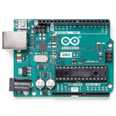
Arduino Uno serves as the brain of your robotic car using Arduino. This versatile board provides sufficient digital pins for motor control and sensor input while offering a beginner-friendly programming environment. The ATmega328P microcontroller processes sensor data and executes your control algorithm.
Motor Driver Module
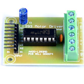
The L293D or L298N motor driver bridges the Arduino and DC motors. Since Arduino pins cannot supply enough current to drive motors directly, this module amplifies control signals while protecting your microcontroller from voltage spikes generated by motor operation.
DC Gear Motors and Wheels
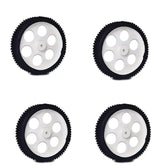
Two DC gear motors with attached wheels form the robot's drivetrain. Key specifications include:
- Gear reduction provides adequate torque for movement while maintaining controllable speeds
- Motors rated between 100-300 RPM offer optimal balance between speed and control
- Attached wheels should have sufficient diameter for ground clearance
IR Sensor Modules
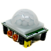
Two or more IR sensor modules detect the line. Pre-assembled modules include both the emitter and detector along with signal conditioning circuitry, simplifying connections and improving reliability. Position these sensors at the robot's front edge, pointing downward toward the surface.
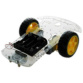
Chassis and Mounting Hardware
A sturdy DIY car chassis holds all components together. Consider these materials:
- Acrylic or metal plates work well, providing mounting points for motors, wheels, the Arduino board, and battery pack
- Include a caster wheel or ball bearing at the rear for stability
- Ensure adequate space for component placement and wire routing
Power Supply
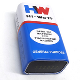
A 7.4V or 9V battery pack powers both the Arduino and motors. Ensure sufficient capacity (at least 1000mAh) for extended operation during testing and demonstrations.
Connecting Wires and Miscellaneous Parts
Quality jumper wires, a breadboard for prototyping, mounting screws, and double-sided tape complete your toolkit for this line following robot project.
Circuit Diagram and Connections Explained
Proper wiring ensures reliable operation of your line follower robot. The circuit consists of three main subsystems: power distribution, sensor input, and motor control.

Power Connections
Connect the battery pack positive terminal to the motor driver's power input and the Arduino's VIN pin. Ground connections are critical:
- Battery ground must connect to Arduino GND
- Motor driver ground connects to the common ground
- All sensor grounds share this common reference
- This prevents erratic behavior caused by floating grounds
Sensor Wiring
Each IR sensor module has three pins with specific connections:
- VCC connects to Arduino's 5V pin
- GND connects to Arduino ground
- OUT connects to digital input pins (typically D2 for the left sensor and D3 for the right sensor)
Some sensor modules include potentiometers for sensitivity adjustment—calibrate these to reliably distinguish between black and white surfaces under your lighting conditions.
Motor Driver Configuration
The L298N motor driver requires multiple connections for proper operation:
- Arduino digital pins D5 and D6 connect to IN1 and IN2, controlling the left motor direction
- Arduino digital pins D9 and D10 connect to IN3 and IN4, controlling the right motor direction
- Enable pins ENA and ENB receive PWM signals from Arduino pins D11 and D12, allowing speed control
- The two DC motors connect to the driver's output terminals, ensuring correct polarity for forward motion
Arduino Code for Line-Follower Robot Project
The Arduino line follower robot code translates sensor readings into motor actions. Here's a structured approach to programming your robot:
Variable Declarations and Pin Configuration
const int leftSensor = 2;
const int rightSensor = 3;
const int leftMotorForward = 5;
const int leftMotorBackward = 6;
const int rightMotorForward = 9;
const int rightMotorBackward = 10;
const int leftMotorSpeed = 11;
const int rightMotorSpeed = 12;

int baseSpeed = 150;
Setup Function
Initialize all pins and establish serial communication for debugging:
void setup() {
  pinMode(leftSensor, INPUT);
  pinMode(rightSensor, INPUT);
  pinMode(leftMotorForward, OUTPUT);
  pinMode(leftMotorBackward, OUTPUT);
  pinMode(rightMotorForward, OUTPUT);
  pinMode(rightMotorBackward, OUTPUT);
  pinMode(leftMotorSpeed, OUTPUT);
  pinMode(rightMotorSpeed, OUTPUT);
  Serial.begin(9600);
}
Main Control Loop
The loop function continuously reads sensors and adjusts motor commands:
void loop() {
  int leftValue = digitalRead(leftSensor);
  int rightValue = digitalRead(rightSensor);

  if (leftValue == LOW && rightValue == LOW) {
    moveForward();
  }
  else if (leftValue == LOW && rightValue == HIGH) {
    turnLeft();
  }
  else if (leftValue == HIGH && rightValue == LOW) {
    turnRight();
  }
  else {
    stopMotors();
  }
}
Motor Control Functions
Define functions for each movement direction:
void moveForward() {
  digitalWrite(leftMotorForward, HIGH);
  digitalWrite(leftMotorBackward, LOW);
  digitalWrite(rightMotorForward, HIGH);
  digitalWrite(rightMotorBackward, LOW);
  analogWrite(leftMotorSpeed, baseSpeed);
  analogWrite(rightMotorSpeed, baseSpeed);
}

void turnLeft() {
  digitalWrite(leftMotorForward, LOW);
  digitalWrite(leftMotorBackward, LOW);
  digitalWrite(rightMotorForward, HIGH);
  digitalWrite(rightMotorBackward, LOW);
  analogWrite(leftMotorSpeed, 0);
  analogWrite(rightMotorSpeed, baseSpeed);
}
This code provides a foundation for your beginner robotics project with Arduino. You can enhance it with proportional control, acceleration curves, or line-loss recovery algorithms as you gain experience.
Step-by-Step Guide to Building the Line-Follower Robot
Understanding how to make a line follower robot requires methodical assembly and testing. Follow these steps to build a line following robot successfully:
Mechanical Assembly
Begin by mounting the DC motors to your chassis using the provided brackets. Key considerations include:
- Position motors parallel to each other with wheels facing outward
- Attach the rear caster wheel or ball bearing for balance
- Ensure the chassis sits level when placed on a flat surface, as tilting affects sensor performance
- Mount the IR sensors at the front edge of the chassis, approximately 5-8mm above the ground surface
- Space sensors 15-20mm apart, centered relative to the chassis width
This positioning allows the robot to detect when the line passes under either sensor.
Electronic Assembly
Secure the Arduino board and motor driver to the chassis using standoffs or double-sided tape, ensuring they won't shift during operation. Position the battery pack for balanced weight distribution—typically at the rear of the chassis.
Follow the circuit diagram to connect all components:
- Use different colored wires for power (red), ground (black), and signals (other colors) to simplify troubleshooting
- Keep wire lengths appropriate to avoid excessive slack or tension
- Route wires away from moving parts like wheels and motors
- Double-check all connections before applying power, as incorrect wiring can damage components
Initial Testing
Before running the complete program, test individual subsystems:
- Upload a simple sketch that reads sensor values and prints them to the Serial Monitor
- Place the robot over black and white surfaces to verify sensors detect the difference
- Test motor control by uploading code that runs each motor independently
- Check rotation direction and speed response for each motor
- Verify that the power supply provides stable voltage under load
Calibration and Tuning
Create a test track using black electrical tape on white poster board or vice versa. Make the initial path straight with gentle curves. The calibration process involves:
- Place your robot on the line and upload the complete control code
- Observe its behavior and adjust the base speed variable if it moves too quickly or slowly
- Fine-tune sensor sensitivity using the onboard potentiometers until the robot reliably follows the path
- Test different lighting conditions to ensure consistent performance
- Make incremental adjustments rather than large changes
Advanced Testing
Gradually increase track complexity with sharper turns and intersections. Modify the code to handle these challenges:
- Consider adding more sensors for better line detection
- Implement PID control algorithms for smoother following behavior
- Add acceleration and deceleration profiles for better control
- Test the robot's performance at different speeds
Why Choose Robocraze Components for Your Robotics Projects
At Robocraze, we understand that the difference between a frustrating experience and an exciting learning journey often comes down to component quality and support.
When you choose our parts for your line following robot project, you're not just buying products—you're investing in a successful robotics education.
Quality You Can Trust
Every component we stock undergoes rigorous testing before reaching our shelves. Our quality standards ensure:
- Arduino boards feature genuine ATmega microcontrollers with stable voltage regulation
- Motor drivers include thermal protection and flyback diodes to prevent damage from inductive loads
- IR sensor modules arrive pre-calibrated with high-quality photodiodes that provide consistent readings
- All electronic components meet international safety and performance standards
This reliability means less time troubleshooting faulty components and more time learning robotics concepts.
Curated Kits for Seamless Integration
We've assembled complete kits specifically designed for building a line follower robot. Benefits include:
- Every component is selected for compatibility, eliminating the guesswork
- Kits include detailed connection diagrams and sample code
- Significantly reduced setup time for beginners
- All necessary hardware and mounting accessories included
This careful curation reflects our experience working with thousands of students and hobbyists who've successfully completed their first robotics projects using our products.
Educational Resources and Support
Purchasing from Robocraze gives you access to comprehensive learning materials:
- Extensive knowledge base featuring video tutorials and project guides
- Step-by-step troubleshooting tips for common issues
- Technical support team consisting of engineers and educators
- Community forums where you can connect with other robotics enthusiasts
Whether you're puzzling over a wiring issue or optimizing your control algorithm, we're here to help you succeed in your beginner robotics project with Arduino.
Competitive Pricing Without Compromise
Quality robotics kits shouldn't break the bank, especially for students and educational institutions. Our approach includes:
- Competitive pricing through direct relationships with manufacturers
- No compromise on component quality or reliability
- Special discounts for bulk orders and educational institutions
- Transparent pricing with no hidden costs
This approach makes STEM learning accessible to a broader audience, supporting our mission to nurture the next generation of engineers and innovators.
Fast Delivery and Hassle-Free Returns
We know the excitement of starting a new robotic project shouldn't be dampened by long shipping times:
- Efficient logistics network ensures rapid delivery across India
- Real-time order tracking for complete transparency
- Secure packaging to prevent damage during transit
- Straightforward return policy in the rare event of issues
Growing with Your Skills
As your robotics journey progresses beyond your first line follower robot, Robocraze continues to support your growth:
- Catalog includes advanced components for complex projects
- From multi-axis robotic arms to autonomous drones
- Regular new product additions based on emerging technologies
- Technical documentation and tutorials scale with project complexity
We're not just a supplier for one project; we're a partner in your ongoing exploration of robotics and embedded systems.
Conclusion
Building a line follower robot represents more than just assembling components and uploading code—it's a gateway into understanding how autonomous systems perceive their environment and make decisions.
This project teaches fundamental concepts that scale from simple robots to sophisticated industrial automation and even autonomous vehicles.
The satisfaction of watching your creation navigate a path independently, making corrections and adjustments based on sensor feedback, provides motivation that no textbook can match.


