All About Gear Motors
Summary
Dive into the world of gear motors with our comprehensive blog, "All About Gear Motors." Explore the fundamental Introduction to gear motors, uncover diverse Gear Motor Types, dissect Critical Internal Elements for optimal performance. Learn the essential Gear Motor Sizing Criteria and discover real-world Use Case Applications. Unlock the secrets to Optimizing Gear Motor Effectiveness for maximum efficiency. In the end, find a satisfying CONCLUSION that ties it all together. Gear up for a journey through the heart of gear motor technology—your gateway to enhanced mechanical prowess! Read more and gear up for success!
Introduction
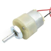
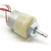
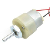
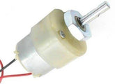
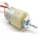
Gear motors are mechanical devices used to increase torque or reduce speed in a powertrain. They accomplish this by incorporating a gearbox that houses a series of gears connected by shafts inside a motor housing. Gearing inside the unit utilizes the physics of torque, speed ratios and power conversion to create optimized mechanical performance.
The gearbox inside the motor housing contains machined steel or plastic cog wheels mounted on shafts and arranged in a series. The cogs feature teeth cut in specific profiles that interlock with mating gears as they rotate. Rotational energy transfers from the motor drive shaft through the progression of gears inside the box before exiting via the slower output shaft. This gearing takes the high native speed from the motor and converts it into increased rotational force at reduced rpm.
Gearboxes arrange into external or internal configurations inside the motor body. Internal drives integrate the gear assembly within the motor body itself for more compact packages. External gearboxes consist of a separate mechanical module bolted onto the motor. While external units take up more space, they allow for more gear stages and ratios. Integrated internal gears however offer simpler, more streamlined setups.

Gear Motor Types
Various gear motor styles provide a broad selection of speed, precision, noise, efficiency, cost and longevity performance options. Common gear motor types include:
1. Helical Gear Motors
Helical gears consist of angular teeth cut at inclines that mesh together along diagonal planes. This orientation provides smooth, quiet operation combined with the capacity for heavy loads. The angled gearing also permits high velocity ratios within compact spaces. Back driving tendency allows reversible functioning.
2. Spur Gear Motors
Spur gears align perpendicular to shafts for power transmission without axial loads. Their straight cut teeth minimize friction, allowing high-efficiency operation. But the square alignment also generates noticeable noise. Spur gears work well for bulk material handling at lower costs.
3. Planetary Gear Motors
Planetaries utilize an epicyclic configuration with a sun gear centered among planetary gears encased within a ring gear. The ingenious layout transmits multiplied torque from a single stage. All gear layers rotate against each other on a fixed carrier arm, producing ratios exceeding 7:1 within tight volumes.
4. Worm Drive Gear Motors
These consist of a steel or thermoplastic worm screw that rotates against a matching worm wheel. The meshing and 90 degree crossing of parts generates substantial speed reductions and torque gains using very few components. Worm drives also offer self-locking ability useful for braking functions.
5. Bevel Gear Motors
Bevel gears cut with conical or angular faces allow for power transmission between intersecting shafts. The right-angled layout suits applications requiring direction changes in the driveline. They handle high speeds and exhibit low noise even under reversing loads.
Also check our gear motor collection which provides a range of gear motors suitable for various applications in robotics and DIY projects.
Critical Internal Elements
The specialized internal components of gear motors include the mechanical parts that enable smooth gearing functionality over millions of revolutions. Vital elements consist of:
- Gears: The machined metal or plastic cog wheels ranging from 10 to 250 mm in diameter that transfer motion. Involute profiles improve meshing, while some worm drives use triangular threading. Materials include alloy steel, bronze, cast iron, acetal homopolymer or nylon polymer.
- Supporting Shafts: Hardened alloy steel spindles ranging from 10 to 100 mm in diameter serve as the rotating axis of gears and worm screws. Shafts withstand axial and radial loads beyond 10 kNm.
- Bearings: Ball or tapered roller bearings with inner and outer steel races and rolling elements support gear shafts, permitting smooth rotation and shaft alignment inside casings. Special coatings minimize friction while maximizing positional integrity.
- Lubrication: Oils or semi-fluid greases protect internal components from corrosion, excessive heat and wear while promoting free motion. Circulation systems foster lubricant flow across bearings and gears.
Gear Motor Sizing Criteria
Correctly matching gear motor specifications to application requirements leads to years of reliable performance. Critical criteria when selecting units includes:
- Output Torque: Compare the torque produced by the motor’s gearing at rated speeds to actual torsional demands of the operating machinery.
- Precision Grade: Finely machined gearing suits highly dynamic tasks needing accuracy, while standard grades work for simpler duties.
- Gear Materials: Metal compositions have higher load capacity and noise ratings than less-expensive polymers used for lighter applications.
- Service Factor: Inbuilt allowance permitting momentary overloads beyond the rated torque without immediate breakdowns.
- Gear Efficiency: The effectiveness of power transfer across the gearing, with higher ratings yielding better energy savings.
Use Case Applications
Gear motors serve an extensive range of demanding equipment applications by optimizing torque and speed:
- Conveyor Lines: Helical and bevel units drive conveying equipment across warehouses, while worm drives empower inclined take-up belts.
- Extrusion Machines: High torque spur and helical gears feed material through dies to create continuous plastic, clay or food extrusions.
- Agitator Vessels: Compact planetary drives offer multiplication for viscous mixing tanks while spur types handle lighter blending.
- Actuation Systems: Worm and planetary gears reduce speed while increasing torque for precise positioning control. Bevels change angles for aircraft flaps.
- Pumps & Compressors: Helical drives withstand pumping pressures and gaseous compression loads across medical, chemical and industrial systems.
- Robots & Cobots: Zero-backlash precision planetary and harmonic gearing facilitates intricate automated movements.
Optimizing Gear Motor Effectiveness
Proper installation, operation and maintenance enhances performance over the working lifespan of gear motors:
- Direct Shaft Coupling: Connecting gear motor output shafts straight to driven equipment shafts improves efficiency over belted or chained links.
- Precision Alignment: Carefully aligning shafts using jigs prevents premature wear of internal gears and bearings due to unnecessary loads.
- Overload Protection: Installing slip clutches or electronic torque limiting controls to protect gears from spike overloads beyond margins.
- Fluid Changes: Replacing gear lubricants regularly as per OEM guidelines significantly extends component longevity.
- Temperature Monitoring: Checking gearbox heat with sensors safeguards against overheating which degrades oil films and bearing sustainability.
Conclusion
Gear motors represent indispensable electromechanical power conversion equipment enabling countless demanding rotational applications. Their internal gearing leverages torque physics to output expanded speed ranges beyond native motor capabilities. With prudent selection, integration and maintenance, industrial users maximize uptime and productivity across installations. Personnel must comprehend operational nuances and use case needs to leverage them effectively.


