


Summary
Learn how to use a joystick module with Arduino UNO, including its pinout, wiring, and code for reading the X-axis, Y-axis, and push button. This tutorial covers INPUT_PULLUP and dead zone calibration to prevent unwanted drift. You will also learn how to control an SG90 servo motor and drive a two-motor robot car using an L298N motor driver.

A joystick module for Arduino is two 10k potentiometers (X and Y) mounted at 90 degrees, plus a push switch under the stick. On an Arduino UNO, each axis reads from 0 to 1023 through analogRead(), and sits at about 512 when the stick is at rest. The switch gives a digital LOW when pressed.
This makes the joystick module one of the cheapest ways to add proportional, two-axis control to a project. In this guide, we wire it to an Arduino UNO, read both axes and the button, then use it to steer a servo and drive a two-motor robot car. We also cover the dead zone, and the reason a "centred" joystick keeps nudging your robot.
What You Need for This Tutorial
- PS2 Joystick Module (dual axis)
- Arduino UNO R3 and a USB cable
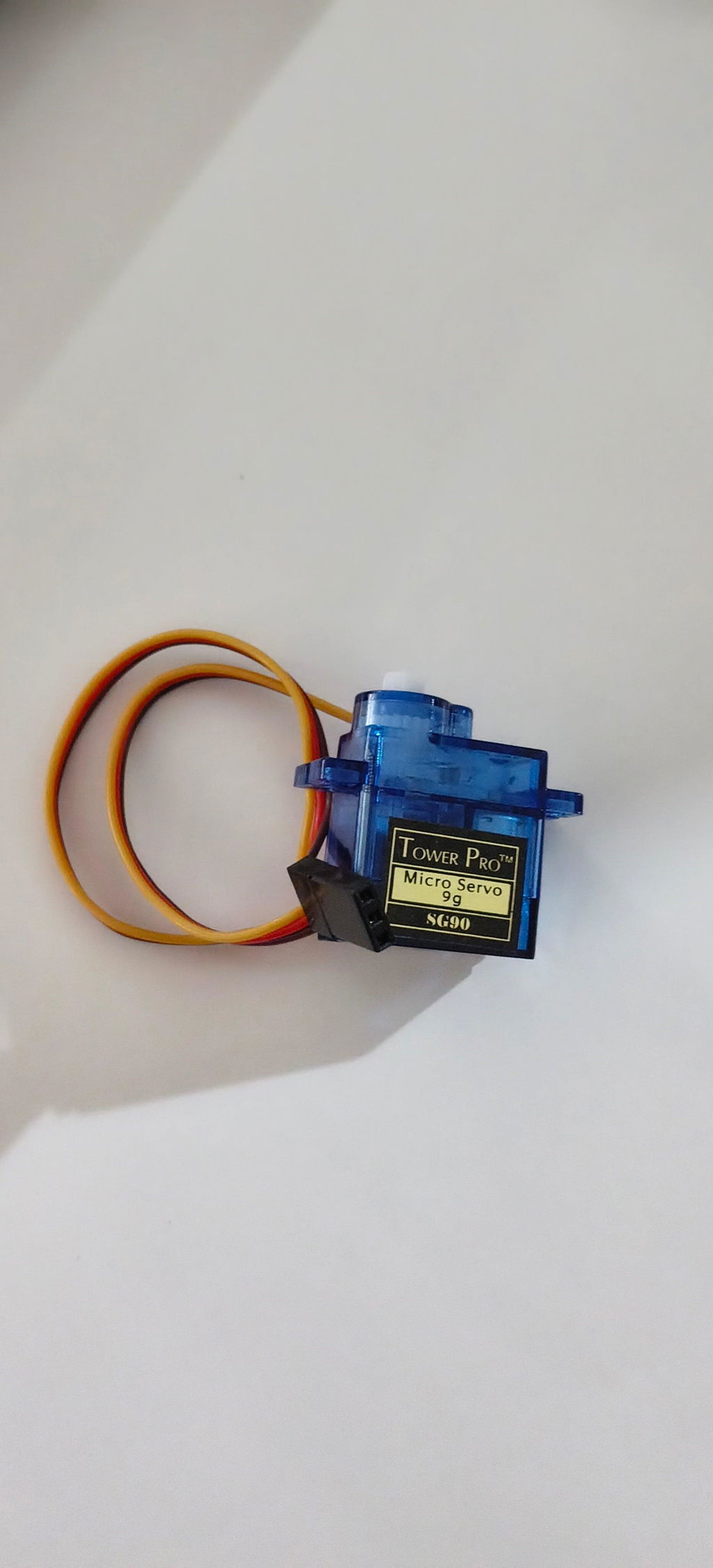
- SG90 Micro Servo Motor (Project 1)
- Male-to-female jumper wires
Browse more options in our Joystick & Keypads collection.
What Is a Joystick Module?
A joystick module is a thumb stick like the one found on a Playstation. It is mounted on a small breakout board with five header pins, and converts the stick's position into two analog voltages and the press of the stick into a digital signal.
Inside, the stick is linked to two potentiometers set at right angles. Moving the stick left or right turns the X potentiometer; moving it up or down turns the Y potentiometer. Each pot works as a voltage divider between 0V and 5V, so the output voltage tracks the stick's position. Springs pull the stick back to the middle, where both outputs sit near 2.5V.
Press the stick down and it closes a small tactile switch underneath. That switch is the SW pin, and it connects to GND when pressed.
| Stick position | X reading (VRx) | Y reading (VRy) |
|---|---|---|
| At rest (centre) | about 512 | about 512 |
| Fully one way on the axis | close to 0 | close to 0 |
| Fully the other way | close to 1023 | close to 1023 |
| Diagonal | both values change together | |
Which direction gives 0 and which gives 1023 depends on how the module is oriented, so always check with the Serial Monitor before writing direction logic. The module on our website runs on 5V and measures 40 x 27 x 15 mm.
Components and Supplies


PS2 Joystick Module Breakout Sensor
- Rs 49/-
- Rs 49/-
-
Rs 59/-


Arduino Uno R3 Original
- Rs 2,750/-
- Rs 2,750/-
-
Rs 3,499/-


3M USB to Micro USB Cable Black
- Rs 138/-
- Rs 138/-
-
Rs 199/-


TowerPro SG90 9G Micro Servo Motor 180° for Arduino & Robotics
- Rs 182/-
- Rs 182/-
-
Rs 239/-


Male to Female Jumper Wires (20cm) (20pcs)
- Rs 28/-
- Rs 28/-
-
Rs 49/-


2A Dual L298N Motor Driver Module with PWM Control
- Rs 165/-
- Rs 165/-
-
Rs 239/-


4WD Smart Robot Car Chassis Kit with Motors for Arduino & Robotics
- Rs 799/-
- Rs 799/-
-
Rs 859/-


HC-05 Bluetooth Module
- Rs 215/-
- Rs 215/-
-
Rs 349/-
Joystick Module Pinout
The joystick module pinout has five pins: two for power, two analog outputs, and one digital switch output.

| Pin | Type | Function | Connects to (UNO) |
|---|---|---|---|
| GND | Power | Ground reference | GND |
| +5V | Power | Supply for both potentiometers (3.3V on 3.3V boards) | 5V |
| VRx | Analog output | Voltage proportional to X (left/right) position | A0 |
| VRy | Analog output | Voltage proportional to Y (up/down) position | A1 |
| SW | Digital output | Push switch; connects to GND when the stick is pressed | D2 |
On some boards, the labels read VCC instead of +5V, or VER and HOR instead of VRy and VRx. The order of pins is the same on almost every PS2-style module, but always read the silkscreen before you wire.
Wiring the Joystick Module to Arduino UNO
Connect the two power pins to the UNO's 5V and GND, the two axes to analog pins A0 and A1, and the switch to digital pin D2. Five male-to-female jumper wires are all you need; no resistors are required.

- GND → GND on the UNO's power header.
- +5V → 5V. The axes are only accurate when the joystick and the ADC share the same 5V reference.
- VRx → A0 and VRy → A1. Any analog pin works, but the code below uses these two.
- SW → D2. The switch has no pull-up resistor of its own on most modules, so we enable the UNO's internal one in code.
Not sure where the analog and power pins are? Our Arduino UNO pin diagram guide labels every header.
Code: Read X, Y, and the Button
This PS2 joystick module Arduino code reads both axes with analogRead(), reads the switch with digitalRead(), and prints all three in a format the Serial Plotter can graph. No library is needed.
// Joystick module: read X, Y and the button (Arduino UNO)
const int X_PIN  = A0;   // VRx
const int Y_PIN  = A1;   // VRy
const int SW_PIN = 2;    // SW (push button)

void setup() {
  Serial.begin(9600);
  pinMode(SW_PIN, INPUT_PULLUP);   // button reads HIGH until pressed
}

void loop() {
  int x = analogRead(X_PIN);              // 0 to 1023
  int y = analogRead(Y_PIN);              // 0 to 1023
  int pressed = (digitalRead(SW_PIN) == LOW) ? 1 : 0;

  // "label:value" pairs give named traces in the Serial Plotter
  Serial.print("X:");       Serial.print(x);
  Serial.print(",Y:");      Serial.print(y);
  Serial.print(",Button:"); Serial.println(pressed * 1023);

  delay(20);
}
Why INPUT_PULLUP for the SW pin?
The SW pin is a bare switch to ground. When the stick is not pressed, nothing drives the pin, so it "floats" and digitalRead() returns random HIGHs and LOWs. INPUT_PULLUP turns on the UNO's internal pull-up resistor (about 20k to 50k), which holds the pin HIGH until the switch pulls it to GND. The result is a clean signal: HIGH when released, LOW when pressed. That is why the code checks for LOW.
See it in the Serial Plotter
Upload the sketch, then open Tools > Serial Plotter at 9600 baud. Move the stick and press it to see the three traces.

- At rest, X and Y sit close to 512.
- Pushing along one axis moves that trace towards 0 or 1023 while the other stays flat.
- The button trace jumps to 1023 only while the stick is pressed; it is scaled up so it shows on the same graph as the axes.
Project 1: Joystick Servo Control
For joystick servo control, the X axis sets the angle of an SG90 micro servo: stick left turns it towards 0°, stick right towards 180°, and the centre holds it at 90°. Pressing the stick snaps it back to 90°.

Keep the joystick wiring from above and add the servo: orange (signal) to D9, red to the 5V rail, brown to the GND rail. One SG90 can run from the UNO's 5V pin; for two or more servos, use a separate 5V supply and join its GND to the UNO's GND. New to servos? Read All About the SG90 Servo Motor first.
// Joystick servo control: X axis sets the SG90 angle (Arduino UNO)
#include <Servo.h>

const int X_PIN     = A0;
const int SW_PIN    = 2;
const int SERVO_PIN = 9;
const int DEAD_ZONE = 40;     // counts either side of centre to ignore

Servo myServo;
int centreX = 512;

void setup() {
  pinMode(SW_PIN, INPUT_PULLUP);
  myServo.attach(SERVO_PIN);
  delay(100);
  centreX = analogRead(X_PIN);  // calibrate: keep the stick still at power-up
}

void loop() {
  int x = analogRead(X_PIN);
  int angle = 90;

  if (x > centreX + DEAD_ZONE) {
    angle = map(x, centreX + DEAD_ZONE, 1023, 90, 180);
  } else if (x < centreX - DEAD_ZONE) {
    angle = map(x, 0, centreX - DEAD_ZONE, 0, 90);
  }

  if (digitalRead(SW_PIN) == LOW) {
    angle = 90;                   // press the stick to snap back to centre
  }

  myServo.write(constrain(angle, 0, 180));
  delay(15);
}
The sketch reads the real centre value at power-up instead of assuming 512, then maps each half of the stick's travel separately. That way the servo reaches the full 0° and 180° even when your joystick rests at 498 or 530. To build a pan-tilt mo`unt, add a second servo on D10 and repeat the same logic with the Y axis on A1.
Project 2: Build a Joystick Controlled Robot Car
A joystick controlled robot car uses one stick for everything: push forward to drive, pull back to reverse, and tilt sideways to steer. The UNO reads the joystick and sends speed and direction signals to an L298N motor driver, which powers the two DC motors.

An Arduino pin can only supply about 20 mA, far too little for a motor, so the L298N does the heavy lifting. If H-bridges are new to you, see What Is a Motor Driver? The quickest way to get the chassis, wheels, motors and driver together is one of our DIY robot car kits.
| L298N pin | Arduino UNO pin | Purpose |
|---|---|---|
| ENA | D5 (PWM) | Left motor speed |
| IN1, IN2 | D7, D8 | Left motor direction |
| ENB | D6 (PWM) | Right motor speed |
| IN3, IN4 | D9, D10 | Right motor direction |
| GND | GND | Common ground with the battery |
| 12V | Battery + (7.4V to 12V) | Motor supply |
Remove the jumpers on ENA and ENB so the UNO's PWM pins can set the speed. Leave the joystick wired exactly as in the first diagram.
// Joystick controlled robot car: UNO + L298N + 2 DC motors
const int X_PIN = A0, Y_PIN = A1, SW_PIN = 2;

// L298N pins (ENA/ENB need PWM pins)
const int ENA = 5,  IN1 = 7, IN2 = 8;    // left motor
const int ENB = 6,  IN3 = 9, IN4 = 10;   // right motor

const int  DEAD_ZONE = 50;
const bool INVERT_Y  = true;   // most modules read LOW when pushed forward

int centreX = 512, centreY = 512;
bool motorsOn = true;

// Turn a raw reading into -255..255, with a dead zone around centre
int axisToSpeed(int raw, int centre) {
  int offset = raw - centre;
  if (abs(offset) <= DEAD_ZONE) return 0;
  if (offset > 0) return map(offset, DEAD_ZONE, 1023 - centre, 0, 255);
  return map(offset, -centre, -DEAD_ZONE, -255, 0);
}

void driveMotor(int en, int inA, int inB, int speed) {
  speed = constrain(speed, -255, 255);
  digitalWrite(inA, speed > 0);
  digitalWrite(inB, speed < 0);
  analogWrite(en, abs(speed));
}

void setup() {
  pinMode(SW_PIN, INPUT_PULLUP);
  int outs[] = {ENA, IN1, IN2, ENB, IN3, IN4};
  for (int p : outs) pinMode(p, OUTPUT);
  delay(100);
  centreX = analogRead(X_PIN);   // stick must be at rest at power-up
  centreY = analogRead(Y_PIN);
}

void loop() {
  // Press the stick to toggle the motors on and off (simple debounce)
  if (digitalRead(SW_PIN) == LOW) {
    motorsOn = !motorsOn;
    delay(250);
    while (digitalRead(SW_PIN) == LOW) {}
  }

  int throttle = axisToSpeed(analogRead(Y_PIN), centreY);
  int turn     = axisToSpeed(analogRead(X_PIN), centreX);
  if (INVERT_Y) throttle = -throttle;

  // Arcade mixing: Y = forward/back, X = steering
  int left  = constrain(throttle + turn, -255, 255);
  int right = constrain(throttle - turn, -255, 255);

  if (!motorsOn) { left = 0; right = 0; }
  driveMotor(ENA, IN1, IN2, left);
  driveMotor(ENB, IN3, IN4, right);
  delay(20);
}
How the Mixing Works
The Y axis becomes the throttle and the X axis becomes the turn amount. The left motor gets throttle + turn and the right motor gets throttle − turn. Push straight forward and both wheels drive at the same speed. Push right and the left wheel speeds up while the right slows, so the car arcs right. Push fully sideways with no throttle and the wheels spin in opposite directions, turning the car on the spot.
If the car drives backwards when you push forward, set INVERT_Y to false. If it turns the wrong way, swap the wires on one motor's terminals. Want to drop the cable? The same mixing works with a phone app in our Bluetooth controlled car with HC-05 tutorial.
Fixing Drift and Dead Zones
A joystick module rarely reads exactly 512 at rest. Typical modules settle anywhere from about 490 to 530, and the value can flicker by a few counts. Feed that straight into a motor and the robot creeps forward or wobbles even when nobody is touching the stick. That creep is called drift.
The fix is a dead zone: a small band around the centre where any reading is treated as zero. Most tutorials map the raw value straight to an output and skip this step, which is why their projects twitch.
// Dead zone helper: returns -255..255, and 0 near the centre
const int DEAD_ZONE = 50;

int withDeadZone(int raw, int centre) {
  int offset = raw - centre;
  if (abs(offset) <= DEAD_ZONE) return 0;          // ignore small movements
  if (offset > 0) return map(offset, DEAD_ZONE, 1023 - centre, 0, 255);
  return map(offset, -centre, -DEAD_ZONE, -255, 0);
}

// In setup(), with the stick untouched:
//   centreX = analogRead(A0);
//   centreY = analogRead(A1);
Two things make this snippet better than a fixed if (x > 550) check:
- It measures the real centre. Reading each axis once at power-up means the code adapts to your particular module.
- It starts from zero at the edge of the dead zone. The output ramps smoothly from 0 instead of jumping to a speed of 30 or 40 the moment you leave the band.
Start with a dead zone of 30 to 50 counts. If the output still twitches at rest, increase it; if the stick feels sluggish near the middle, reduce it. Other causes of drift worth checking:
| Symptom | Likely cause | Fix |
|---|---|---|
| Centre value wanders as motors run | Motor noise on the 5V line | Power motors from a separate battery; keep the grounds joined |
| Readings jump randomly | Loose jumper or floating pin | Re-seat wires; make sure VRx/VRy go to analog pins |
| Button triggers by itself | SW pin floating | Use INPUT_PULLUP
|
| Axis never reaches 0 or 1023 | Module powered from 3.3V, or worn potentiometer | Use 5V on the UNO; scale with the measured min and max |
Conclusion
The joystick module gives your Arduino two analog axes and a button for the price of a few jumper wires. Read X and Y with analogRead(), use INPUT_PULLUP for the switch, measure the centre at power-up, and add a dead zone so the output is truly zero at rest. With those basics in place, the same few lines of code can aim a servo, steer a robot car, or drive a pan-tilt camera mount.
Build the full robot car. Get the chassis, motors, wheels and driver in one box. Browse DIY car kits, then add a joystick module to take control.
 Chat