


Summary
We compare the TCS34725 and TCS3200 colour sensors for Arduino: how each works, wiring, code and calibration. The TCS34725 is our pick for most projects, thanks to two-wire I2C, an IR-blocking filter and cleaner RGB values. We finish with a simple one-servo colour sorting machine you can build this weekend.

We recommend the TCS34725 for most Arduino projects. It talks I2C over just two wires, has an on-chip IR-blocking filter, and gives cleaner, more repeatable RGB values. The TCS3200 outputs a square-wave frequency, needs four control pins (S0 to S3) plus an output pin, and suits simple colour detection where rough readings are enough.
Colour sensing is where Arduino projects start to feel like real machines: sorters that drop red sweets in one bin and blue in another, robots that react to coloured markers, lamps that copy the colour of whatever you hold up. Two sensors power most of these builds. In this guide we put the TCS34725 vs TCS3200 head to head, wire both to an Arduino UNO, show how to calibrate them, and finish with a colour sorting machine you can build this weekend. New to sensors? Start with our guide to Arduino sensor types and applications.
Quick Verdict
For accurate colour readings with the least wiring, our pick is the TCS34725. If you only need to tell a few bold colours apart and you already have a TCS3200 in your kit, it will do the job. Here is how we compare the two:
| Feature | TCS34725 | TCS3200 / TCS230 |
|---|---|---|
| Output | Digital 16-bit values for red, green, blue and clear | Square wave whose frequency rises with light intensity |
| Interface | I2C (SDA, SCL), address 0x29 | S0, S1, S2, S3 control pins + OUT |
| Arduino pins used | 2 | 5 (OE tied to GND) |
| IR-blocking filter | Yes, on-chip | No |
| Sensing array | 3 x 4 photodiodes (R, G, B, clear) | 8 x 8 photodiodes (16 each of R, G, B, clear) |
| Tuning | Gain 1x / 4x / 16x / 60x, adjustable integration time | Output scaling 2% / 20% / 100% |
| Dynamic range | 3,800,000:1 | Limited; saturates in bright light |
| Supply (module) | 3.3V to 5V | 2.7V to 5.5V |
| Onboard light | 1 white LED | 4 white LEDs |
| Extras | Interrupt pin, lux and colour temperature | None |
| Arduino code | Ready library (Adafruit TCS34725) | Manual pulseIn() timing |
| Best for | Sorting machines, colour matching, anything that must be repeatable | Simple colour detection, classroom demos |
Grab your sensor
| TCS34725 RGB Colour Sensor | TCS3200D / TCS230 Colour Sensor | |
|---|---|---|
| Image |  |
 |
| Why pick it | Cleaner RGB values, 2-wire I2C, IR filter built in | Bright 4-LED ring, easy to understand, great for learning |
| Buy | Shop the TCS34725 → | Shop the TCS3200 → |
Want to compare more options? Browse our full range of light, colour and camera sensors.
How a Colour Sensor Works
Every RGB colour sensor works on one simple idea: an object looks red because it reflects red light and absorbs most of the green and blue. Shine white light on it, measure how much of each colour bounces back, and you know its colour.
Inside both sensors is a grid of tiny photodiodes. Each one sits under a red, green, or blue filter, and some have no filter at all (the "clear" channel, which measures total brightness). The difference lies in what happens next. The TCS34725 feeds each channel into a 16-bit analog-to-digital converter and hands your Arduino clean numbers over I2C. The TCS3200 turns the light into a square wave, and your Arduino measures how fast that wave pulses: more light means a higher frequency and a shorter pulse.

The filtered photodiodes are the heart of it; everything after them is just turning light into numbers your code can compare.
Photodiodes also pick up infrared light, which you cannot see but which shifts the readings. The TCS34725 has an IR-blocking filter built into the chip, so its numbers stay closer to what your eyes see. The TCS3200 has none, which is a big reason its readings change so much between a sunny window and a tube light.
Components and Supplies


TCS34725 RGB Color Sensor
- Rs 324/-
- Rs 324/-
-
Rs 449/-


Color Recognition Sensor Module TCS3200D/TCS2300
- Rs 689/-
- Rs 689/-
-
Rs 849/-


TCS34725 RGB Color Recognition Light Sensor Module
- Rs 319/-
- Rs 319/-
-
Rs 444/-


Arduino Uno R3 Original
- Rs 2,750/-
- Rs 2,750/-
-
Rs 3,499/-


Arduino Uno R3 Board compatible
- Rs 429/-
- Rs 429/-
-
Rs 699/-


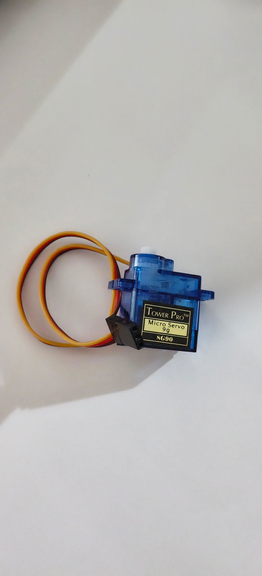
TowerPro SG90 9G Micro Servo Motor 180° for Arduino & Robotics
- Rs 182/-
- Rs 182/-
-
Rs 239/-


Jumper Wire Set - M2M, M2F, F2F (40 pcs each)
- Rs 164/-
- Rs 164/-
-
Rs 169/-


400 Point Solderless Breadboard (Half Breadboard)
- Rs 39/-
- Rs 39/-
-
Rs 69/-
TCS34725: Wiring and Code
The TCS34725 is the one we recommend for beginners. Four jumper wires, one library, and you are reading colours in under ten minutes. The chip itself runs at 3.3V, but the module has an onboard regulator, so you can power it straight from the UNO's 5V pin.
| TCS34725 pin | Arduino UNO pin | What it does |
|---|---|---|
| VIN | 5V | Powers the module |
| GND | GND | Common ground |
| SDA | A4 | I2C data |
| SCL | A5 | I2C clock |
| LED | Not connected | LED stays on; tie to GND to switch it off |
| INT | Not connected | Optional interrupt output |

Only two signal wires are used, so the rest of your UNO's pins stay free for servos, displays and buttons.
Install the library: in the Arduino IDE, open Sketch → Include Library → Manage Libraries, search for Adafruit TCS34725, and click Install. It works with the common blue TCS34725 boards too.
TCS34725 Arduino code: this sketch prints normalised R, G, and B values (0 to 255) plus the raw clear channel to the Serial Monitor at 9600 baud.
#include <Wire.h>
#include "Adafruit_TCS34725.h"

// 50 ms integration, 4x gain: a good start for objects 1-2 cm away
Adafruit_TCS34725 tcs = Adafruit_TCS34725(TCS34725_INTEGRATIONTIME_50MS, TCS34725_GAIN_4X);

void setup() {
  Serial.begin(9600);
  if (!tcs.begin()) {
    Serial.println("TCS34725 not found. Check your wiring!");
    while (1);
  }
  Serial.println("TCS34725 ready");
}

void loop() {
  uint16_t r, g, b, c;
  tcs.getRawData(&r, &g, &b, &c);

  // Divide by the clear channel so overall brightness matters less
  int red   = (float)r / c * 255;
  int green = (float)g / c * 255;
  int blue  = (float)b / c * 255;

  Serial.print("R: ");  Serial.print(red);
  Serial.print("  G: "); Serial.print(green);
  Serial.print("  B: "); Serial.print(blue);
  Serial.print("  Clear: "); Serial.println(c);

  delay(300);
}
If you see "TCS34725 not found", swap SDA and SCL first; it is the most common mistake. Readings that sit near the maximum mean the sensor is saturating: we suggest dropping the gain to 1x or shortening the integration time.
TCS3200: Wiring and Code
The TCS3200 needs more wires, but we like it as a teaching sensor because it shows exactly how colour sensing works. You pick which colour filter is active with S2 and S3, then time the output pulse. No library needed.
| TCS3200 pin | Arduino UNO pin | What it does |
|---|---|---|
| VCC | 5V | Powers the module and its 4 LEDs |
| GND | GND | Common ground |
| OE | GND | Output enable; LOW keeps the output on |
| S0 | D4 | Frequency scaling |
| S1 | D5 | Frequency scaling |
| S2 | D6 | Colour filter select |
| S3 | D7 | Colour filter select |
| OUT | D8 | Square-wave output |

Five of the UNO’s digital pins go to the sensor, so we suggest planning around them if the project also drives motors or a display
The control pins work as two small switch panels:
| S0 | S1 | Output scaling | S2 | S3 | Active filter |
|---|---|---|---|---|---|
| LOW | LOW | Power down | LOW | LOW | Red |
| LOW | HIGH | 2% | LOW | HIGH | Blue |
| HIGH | LOW | 20% (use this with Arduino) | HIGH | LOW | Clear (no filter) |
| HIGH | HIGH | 100% | HIGH | HIGH | Green |
TCS3200 Arduino code: this sketch reads the pulse width for each filter and prints it at 9600 baud. Remember: a smaller number means more of that colour.
// TCS3200 / TCS230 colour sensor with Arduino UNO
#define S0 4
#define S1 5
#define S2 6
#define S3 7
#define OUT 8

int readChannel(int s2, int s3) {
  digitalWrite(S2, s2);
  digitalWrite(S3, s3);
  delay(20);                  // let the filter settle
  return pulseIn(OUT, LOW);   // pulse width in microseconds
}

void setup() {
  pinMode(S0, OUTPUT); pinMode(S1, OUTPUT);
  pinMode(S2, OUTPUT); pinMode(S3, OUTPUT);
  pinMode(OUT, INPUT);

  digitalWrite(S0, HIGH);     // 20% frequency scaling
  digitalWrite(S1, LOW);
  Serial.begin(9600);
}

void loop() {
  int red   = readChannel(LOW, LOW);
  int green = readChannel(HIGH, HIGH);
  int blue  = readChannel(LOW, HIGH);

  Serial.print("R: ");  Serial.print(red);
  Serial.print("  G: "); Serial.print(green);
  Serial.print("  B: "); Serial.println(blue);

  delay(300);
}
Hold a red card under the sensor and the R value should drop well below G and B. Raw pulse widths are hard to compare though, which is why we recommend calibrating before trusting the numbers.
Calibration Tips (Lighting, Distance, White Balance)
Calibration is what turns a colour sensor from "sort of works" into "works every time". Get these three things right. For a deeper dive, read our guide on how to calibrate sensors properly.
- Lock down the lighting. Ambient light is the number one reason colour sensor readings go wrong. We suggest keeping the onboard LED on and surrounding the sensor with a short black shroud: a piece of black straw, heat-shrink tube, or a 3D-printed cap works well. This matters even more for the TCS3200, which has no IR filter.
- Fix the distance. We recommend keeping the object about 1 to 2 cm away, where both sensors read best. The exact number matters less than keeping it the same every time, so mount the sensor at a fixed height or guide objects into a fixed slot.
- Do a white balance. Every LED, every module and every enclosure is slightly different. Take one reading of a white card and one of a black card, then scale every reading between those two points so each channel runs from 0 to 255.
For the TCS34725, raw counts go up with more light:
// Replace with your own black-card (min) and white-card (max) readings
const uint16_t rMin = 120, rMax = 2100;
const uint16_t gMin = 130, gMax = 2300;
const uint16_t bMin = 110, bMax = 1900;

int cal(uint16_t raw, uint16_t lo, uint16_t hi) {
  return constrain(map(raw, lo, hi, 0, 255), 0, 255);
}

// red = cal(r, rMin, rMax); green = cal(g, gMin, gMax); blue = cal(b, bMin, bMax);
For the TCS3200, pulse widths go down with more light, so the mapping flips:
// Replace with your own white-card (min pulse) and black-card (max pulse) readings
const int rWhite = 25, rBlack = 210;
const int gWhite = 27, gBlack = 230;
const int bWhite = 21, bBlack = 180;

int cal(int raw, int white, int black) {
  return constrain(map(raw, white, black, 255, 0), 0, 255);
}
After calibration, the correct channel should clearly lead the other two on a red, green or blue card. Thanks to its IR-blocking filter, the TCS34725 usually keeps the off-colour channels lower than the TCS3200 does, which gives a sorter more margin on in-between shades like orange, pink and purple.
Once calibrated, we suggest deciding the colour by which channel is highest and by how far it leads. If the lead is under about 30 points, treat it as "unknown" and take another reading instead of guessing.
Project: Colour Sorting Machine With a Servo
We designed this colour sorting machine with Arduino to use just one SG90 servo. The servo turns a disc with a single pocket in it. The pocket picks up a sweet under a feed tube, carries it under the TCS34725, then stops over one of three holes in the base plate so the sweet drops into the right bin.
Parts list
| Part | Qty | Shop |
|---|---|---|
| TCS34725 RGB colour sensor | 1 | Buy now |
| SG90 micro servo motor | 1 | Buy now |
| Arduino UNO R3 (compatible) | 1 | Buy now |
| Jumper wires + breadboard | 1 set | |
| Cardboard, MDF or 3D-printed disc, base plate and feed tube | 1 | |
| Three small cups for bins | 3 |
New to the SG90? Our complete SG90 servo guide covers its wires, angles and torque.
How it works

The sensor only decides when one channel clearly beats the others; otherwise, it reads again (up to three times) before sending the disc back to the feed.
Build it
- Cut a 10 cm disc with one pocket near its edge, just big enough for one sweet. Fix it to the servo horn.
- Mount the servo under a base plate. Cut three holes in the plate at 100°, 140° and 180° from the feed position, and put a cup under each.
- Fix a vertical feed tube over the 0° position. The solid disc blocks it until the pocket comes round.
- Mount the TCS34725 over the 50° position, facing down, about 1.5 cm above the pocket, inside a black shroud.
- Wire the sensor as shown earlier. Connect the servo's orange wire to D9, red to 5V, and brown to GND.
The code
#include <Wire.h>
#include <Servo.h>
#include "Adafruit_TCS34725.h"

Adafruit_TCS34725 tcs(TCS34725_INTEGRATIONTIME_50MS, TCS34725_GAIN_4X);
Servo disc;

// Disc angles: feed tube, sensor and the three bin holes
const int FEED = 0, SENSE = 50, RED_BIN = 100, GREEN_BIN = 140, BLUE_BIN = 180;

// Your white/black calibration values (see the Calibration section)
const uint16_t rMin = 120, rMax = 2100;
const uint16_t gMin = 130, gMax = 2300;
const uint16_t bMin = 110, bMax = 1900;

int cal(uint16_t raw, uint16_t lo, uint16_t hi) {
  return constrain(map(raw, lo, hi, 0, 255), 0, 255);
}

void setup() {
  Serial.begin(9600);
  disc.attach(9);
  disc.write(FEED);

  if (!tcs.begin()) {
    Serial.println("Sensor not found");
    while (1);
  }
}

void loop() {
  disc.write(FEED);  delay(600);   // a sweet drops into the pocket
  disc.write(SENSE); delay(600);   // carry it under the sensor

  int target = -1;
  for (int tries = 0; tries < 3 && target < 0; tries++) {
    uint16_t r, g, b, c;
    tcs.getRawData(&r, &g, &b, &c);

    int R = cal(r, rMin, rMax);
    int G = cal(g, gMin, gMax);
    int B = cal(b, bMin, bMax);

    int best   = max(R, max(G, B));
    int lowest = min(R, min(G, B));
    int second = R + G + B - best - lowest;

    if (best - second >= 30) {          // a clear winner
      if (best == R)      target = RED_BIN;
      else if (best == G) target = GREEN_BIN;
      else                target = BLUE_BIN;
    }
    delay(100);
  }

  if (target > 0) {
    disc.write(target);                 // pocket over the right hole
    delay(700);                         // let the sweet drop
  }
}
If the servo jitters or the UNO resets when it moves, we recommend powering the servo from a separate 5V supply (with a shared GND) or add a 470 µF capacitor across its power pins.
Conclusion
In the TCS34725 vs TCS3200 debate, the TCS34725 is our pick for most Arduino projects: two wires, an IR filter, cleaner calibrated readings and a library that does the heavy lifting. The TCS3200 still earns its place on the bench for quick colour detection and for learning how colour sensing really works. Whichever you pick, calibrate it, shield it from room light and keep the distance fixed, and it will reward you with readings you can trust.
Ready to build? Grab the TCS34725 RGB colour sensor or the TCS3200 colour sensor, add an SG90 servo and an Arduino UNO, and your colour sorting machine is a weekend away. Still choosing parts for your first build? Our best sensors for Arduino beginners guide has you covered.
Built something cool with a colour sensor? Share it with us and tag Robocraze, we love seeing what you make!
 Chat