Interfacing PIR Motion Sensor with Arduino
Summary
Motion detection has become an essential component in modern electronics, from security systems to automated lighting. The PIR (Passive Infrared) sensor offers a simple yet effective way to detect movement in its vicinity.
When paired with Arduino, it creates a powerful combination for building intelligent, responsive systems. This guide will walk you through everything you need to know about connecting and programming a PIR sensor with Arduino.

What Is a PIR Motion Sensor?
The PIR Motion Sensor monitors the infrared radiation levels in its field of view, waiting for something warm-blooded, like a human or animal, to pass by. The moment it detects a change in infrared energy, it springs into action.
Unlike other kinds of sensors, the PIR Motion sensor doesn't emit anything. There are no infrared beams or radio waves shooting out. It just passively observes. That's where the "Passive" in PIR comes from. Instead, it detects using the pyroelectric material.

The pyroelectric material generates electricity when exposed to heat. When you walk past it, your body heat creates a rapid change in the infrared radiation pattern, and the sensor picks up on this shift.
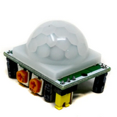
Most PIR sensors come packaged in white dome-shaped modules. Inside that dome sits a Fresnel lens. These segmented, faceted lenses look like dozens of tiny bubbles.
This lens divides the detection area into multiple zones, making the sensor far more sensitive to movement across its field rather than just straight-on approaches.
The detection range typically extends from 3 to 7 meters. The field of view usually spans around 120 degrees, creating a cone-shaped detection zone. Some sensors also include adjustable potentiometers that let you fine-tune sensitivity and the duration the output signal stays high after detecting motion.
Working Principle of a PIR Sensor
The sensor contains two infrared-sensitive elements positioned side by side. In a stable environment with no movement, both elements receive the same amount of infrared radiation, and their outputs cancel each other out. The sensor remains in a low state.
When motion occurs, the scenario changes dramatically. Imagine someone walking across the sensor's field of view. First, one sensing element detects the infrared signature of the moving person, while the other doesn't, creating an imbalance.
As the person continues moving, the second element picks up the heat signature. This differential change triggers the sensor's internal comparator circuit, which then drives the output pin high.
The sensor includes built-in signal processing circuitry. This typically consists of:
- A high-gain operational amplifier that boosts the tiny electrical signals from the pyroelectric elements
- A comparator that converts the analog signal into a digital output
- Timing circuitry that controls how long the output remains high
- Optional retriggering logic that can extend the detection signal if motion continues
Most sensors operate in one of two modes. In repeatable trigger mode, the output stays high as long as motion continues within the detection zone. In non-repeatable trigger mode, the output goes high for a preset time and won't trigger again until that period expires, regardless of continued motion.
Components Required for This Project
Make sure you have the following components before you get started with the project:
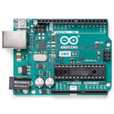
- Arduino board (Uno, Nano, or Mega work perfectly)
- PIR Motion Sensor module (HC-SR501 is commonly available)
- LED (any color, typically red or green)
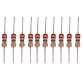
- 220-ohm resistor (for LED current limiting)
- Jumper wires (male-to-male and male-to-female)
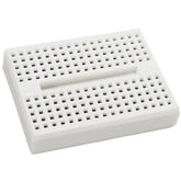
- Breadboard (for prototyping connections)
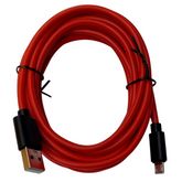
- USB cable (for programming and powering the Arduino)
Optional but recommended components include a buzzer for audio alerts and a relay module if you plan to switch higher-voltage devices. You can build a functional motion detection using Arduino with just a handful of inexpensive components available at any electronics store.
Circuit Diagram for Interfacing PIR Sensor with Arduino

Let's break down what's happening in this circuit, because understanding the connections makes building it ten times easier.
Looking at the image, you've got two main players here: the HC-SR501 PIR sensor sitting at the top and the Arduino Uno board below it. Three wires connect them together and that's all it takes to get motion detection working.
Looking at this circuit, you've got the HC-SR501 PIR sensor at the top connected to the Arduino Uno below it.
Here's what's happening with the three wires:
- Black wire (GND): Runs from the sensor's left pin to Arduino's ground—this completes the circuit
- White wire (VCC): Middle pin connects to Arduino's 5V output, powering up the sensor
- Red wire (Signal): Right pin goes to digital pin 7, sending HIGH when motion's detected
PIR Sensor Pin Configuration and Connections
The HC-SR501 module keeps things simple with just three pins to work with. Once you know what each one does, you're halfway there.
The three pins break down like this:
- VCC (Power): Supplies operating voltage between 4.5V to 12V. Most projects use the Arduino's 5V output, which works perfectly
- GND (Ground): Completes the electrical circuit. Connect this to any Arduino ground pin
- OUT (Signal): The digital output pin that goes HIGH (3.3-5V) when motion's detected, LOW otherwise
Arduino Code for PIR Motion Sensor
The code that brings your Arduino with PIR Motion Sensor to life is quite simple. Here's a complete, working program with detailed explanations:
const int pirPin = 2;        // PIR sensor output connected to pin 2
const int ledPin = 13;       // LED connected to pin 13
int pirState = LOW;          // Start assuming no motion detected
int val = 0;                 // Variable to store sensor status

void setup() {
  pinMode(ledPin, OUTPUT);   // Set LED pin as output
  pinMode(pirPin, INPUT);    // Set PIR pin as input
  Serial.begin(9600);        // Initialize serial communication
  delay(2000);               // Give sensor time to stabilize
  Serial.println("PIR Sensor Ready");
}

void loop() {
  val = digitalRead(pirPin); // Read the sensor output

  if (val == HIGH) {         // Motion detected
    digitalWrite(ledPin, HIGH);

    if (pirState == LOW) {
      Serial.println("Motion Detected!");
      pirState = HIGH;
    }
  }
  else {                     // No motion
    digitalWrite(ledPin, LOW);

    if (pirState == HIGH) {
      Serial.println("Motion Ended");
      pirState = LOW;
    }
  }
}
The code architecture follows a simple but effective pattern. During setup, pin modes are configured and the serial monitor initializes for debugging. The 2-second delay allows the PIR sensor to calibrate itself—critical for accurate operation.
The main loop continuously polls the PIR sensor's digital output. When motion is detected (HIGH signal), the LED illuminates and a message prints to the serial monitor. The pirState variable prevents flooding the serial monitor with repeated messages while motion continues.
You can enhance this basic code in numerous ways. Adding a buzzer creates an audible alarm. Implementing a relay module allows controlling lights, fans, or other AC-powered devices.
For more sophisticated applications, consider adding a timer that sends notifications if motion is detected during specific hours, or integrate multiple sensors to cover larger areas.
The serial monitor output provides valuable debugging information. Open it through the Arduino IDE (Tools → Serial Monitor) and set the baud rate to 9600. You'll see real-time status updates showing exactly when motion starts and stops, helping troubleshoot any detection issues.
Conclusion
Building a motion detection system by interfacing a PIR sensor with Arduino opens doors to countless practical applications. From energy-efficient automatic lighting to security systems, the possibilities extend only as far as your imagination.
The straightforward hardware connections and simple code make this project accessible to beginners while providing enough flexibility for advanced implementations. With this foundation, you're equipped to create responsive, intelligent systems that react to human presence.


