How to check electronic components with Multimeter
Summary
Unlock the secrets of electronic components with our latest blog on "How to Check Electronic Components with a Multimeter." Dive into the essentials with a comprehensive introduction, setting the stage for testing success. Learn the art of preparing for component testing, explore tips for testing common passive components, and discover the nuances of validating semiconductor components. Uncover the mysteries of advanced components that demand specialized testing. We guide you through interpreting results effectively. Don't miss the conclusion, where we tie it all together. Master the multimeter, unravel electronic complexities, and elevate your testing prowess now! Click for a journey into the heart of electronic diagnostics.
Introduction
The Multimeter - An Essential Diagnostics Tool
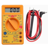
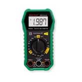
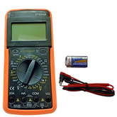
No toolbox lacks a hammer, no workshop omits a ruler. Similarly, every electronics workbench requires a multimeter. Measuring voltage, current, resistance, and continuity verifies proper functioning, validates schematics, and diagnoses faults. When soldering skill connects components correctly but the circuit still fails, the multimeter illuminates electron flow. Understanding this indispensable tool empowers repair and reliability.

Preparing for Component Testing Success
Choosing Measurement Modes
Multimeters include numerous settings like voltage, current, resistance, continuity, capacitance, frequency, and more. Select modes purposefully matching expectations - don't use voltage settings probing resistance. Typically diode test or resistance works for checking electronics parts. Continuity beeps upon detecting a completed circuit across probe tips. Capacitance modes directly measure storage values while frequency settings characterize oscillator outputs. Start simple then advance as knowledge grows.
Configuring Ranges
Auto-ranging meters set themselves but manually controlled units require appropriate range adjustment. Set the scale just above an expected reading. For example 1-10K ohms for a 3k resistor. Avoid leaving ranges on highest settings which reduces accuracy on low readings. Narrow the span for better precision. Understanding circuit characteristics informs proper range selection. Confusing scale multipliers also throws measurements off. For resistors under 1000 ohms, readings display in plain ohms. Values above use kilo ohms (K ohms). Tiny resistors even reach mega ohms.
Verifying Probe Integrity
Quality probes enhance measurements by carrying signals cleanly. Inspect connectors ensuring solid attachment to meter measuring points, then validate by touching probes together to test for continuity. Replace worn probes introducing measurement uncertainty through increased resistance or susceptibility to electromagnetic interference. Confirm rated current and voltage levels match application needs. Probe material and shape also matter - sharp tips reach into breadboards while broader spades grab component leads reliably.
Interpreting Readings
Make solid contact before accepting displayed values by monitoring for stability and averaged input. orientations in reference to device terminals contributes to inconsistencies. Beware readings fluctuating moderately around an average value suggest loose connections or electromagnetic noise sources. If stuck exactly on an upper or lower range limit, shift scales for better resolution. Slight overloads display clearly but avoid pushing equipment past safety ratings. Knowledge of expected results provides meaningful verification.
Testing Common Passive Components
Resistors

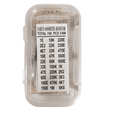
Instead of directly labeling ohm values, small resistors use color codes along their bodies to specify nominal resistance and tolerance. Standard coding decodes as: [1st, 2nd Digits][Multiplier][Tolerance]. For example, grey, red, black, gold decodes to 82 x 100 ohms = 8.2K ohms with 5% tolerance. When measuring, result should land between 7.8K and 8.6K ohms. Band decoding tables are widely available and essential for identification. Small differences greatly impact circuit performance.
After decoding bands, test measured values in resistance mode. Compare to rating accounting for tolerance ranges - resistors often group into 5%, 10% or even 20% tolerance ranges depending on application, with lower tolerances increasing cost. If original senses as too far out of spec or inconsistent across similar parts, additional testing helps determine if the part drifted or was mismarked. Matching measurements with coding gives high confidence in sourced components.
Capacitors
As charge storage tanks for electronics, verifying capacitor values ensures proper operation for pulse timing, filtering, and backup power for clock or BIOS memory. Use a capacitance meter by charging then timing discharge rates. Match new measurements against part specifications and record baseline values for future trend analysis providing predictive guidance as electrolytic and other capacitors slowly decrease capacity over operating life. Out of spec low values or inconsistent measurements suggest mismarked or counterfeit parts not meeting labeled ratings.
A perfect capacitor blocks any current flow when voltage applied, acting as an open circuit until pulse demands instant discharge. But real-world leakage slowly dissipates stored energy prematurely impacting timing circuits. Detect discharge issues using resistance measurement mode immediately after charging up a cap. Low resistance indicates current leakage paths demanding replacement of faulty parts before connecting in circuit applications sensitive to exact pulse control. High measured resistance, often near overload values, proves no electron escape routes exist to undermine capacitor function.
Diodes
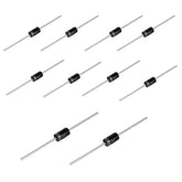
As polarized one-way current gates, properly orienting diodes attaches anode positive and cathode negative terminals correctly so electrons flow ideal direction. Identifier stripes on the bodies indicate cathode pins needing connection to negative voltages. Some diode schematic symbols also include polarity markings though often omitted when clearly flowing left-to-right onto a component input. Finding data sheets definitively identifies terminals needing correct positioning to avoid blocking flow under forward bias conditions expected for signal controls.
In the pass-through direction, silicon diode voltage drops range between 0.6v-0.7v while germanium diodes trigger around 0.2 to 0.3 volt drops. Connected backwards, measurements overload or result in high resistance blocking flow. Zener diodes regulate voltages so may indicate higher set reverse breakdown activation from 5v up to 200v. If multimeter readings appear matched both directions, the diode likely failed as a short circuit no longer gating properly. Monitoring changes over retests assess aging before complete failure.
Validating Semiconductor Components
Transistors

Connecting NPN or PNP power transistor terminals properly ensures amplifying characteristics instead of instant failure from shorts. Analyzing part markings definitively identifies emitter, base, and collector legs. Lacking markings, a multimeter in diode check probes base-emitter and base-collector combinations to categorize conduction detecting NPN vs PNP types based on detected paths. No paths flipping probes imply FET construction with gate channel activation. Attempting to pass signal flows through transistors before identifying orientation risks damaging electronics parts.
More advanced semiconductors characterize internal gain by injecting signals then measuring amplification factors. For basic usage validation, test any path conduction across all three transistor terminals. Monitor base-emitter junction thresholds over time providing predictive guidance on lifespan. Benchmarking air and thermal conditions provides contextual data reconstruction the operating circumstances potentially accelerating wear. Install socketed parts whenever possible for simplified testing before integration into circuit designs.
Integrated Circuits

Trust but verify IC pinouts actually match package diagrams with multimeter continuity tests across internal connected pins. 555 timers should connect trigger to output stages and join reset pins to discharge paths. 741 operational amplifiers properly link negative feedback pins surrounding internal differential pairs. Don't assume stamped numbers appear properly positioned. Foolproof IC validation rejects risky mis wired components threatening safe operation.
Salvaged integrated circuits live dangerously subjected to hormonal faults absent protective circuitry. Generic manufacturers cut corners on legacy chips like 555 timers and 741 Op Amps driving down cost while increasing function risk from loose tolerances or contaminated etching material introducing charge carrier mobility impacts. Rapid continuity screening across key pins establishes baseline validation signatures distinguishing authentic originals from questionable counterfeits components with hopefully robust lifetimes.
Advanced Components Demand Specialized Testing
Relays
Electromagnets pull armatures connecting circuits through metal contact terminals. Measuring coil resistances guides relay power supply sizing by matching voltage and current to activate reliably. Expect substantial manufacturer variability generally ranging between a few ohms for high current devices up to 1000 ohms for low power relays. Keep within 20% of ratings to account for temperature fluctuations. Much lower resistance hints at shorts undermining magnetic coil strength.
Once activated, relay contacts shuttle signals from input to output. Continuity testing while powering coils verifies clean connections. Expect resistance measurements below overload just before reaching direct shorts. If contact resistance measures too high, induction fields may inadequately engage. Continuity indicates properly mated connections while overload suggests risk of contact issues or oxidation increasing chances relays may fail stuck open.
Transformers
Transformers adjust voltages passing signals between circuits. Test winding continuity ensuring copper traces connect end-to-end. Expect very low resistance similar to direct shorts. Balance measurements across separated windings to verify symmetry. Any single high resistance trace fails load balancing risking excess heat threatening insulation meltdowns. Small variances verify tightly tolerance windings.
Insulation separates crossing winding layers carrying differing voltages. If insulation gaps permit contact between traces, extreme over currents damage transformers. Measure insulation resistance by powering off secondary coils before probing primary winding continuity to shared cores. While megohm measurements are positive, overload readings signal direct shorts. Discontinue using damaged transformers at risk of catastrophic failure when reactivated. Replace units measuring low insulation resistance readings.
Cables
Video signals pass through coaxial cables between electronic components
. Cat5 or Cat6 connects network devices. USB, HDMI, and countless connector types shuttle data relying on perfect end-to-end continuity. Test cables by probing matched wire pairs at both termination plugs. continuity beeps verify needed electrons flow allowing flawless communication. No connection indicates breaks demanding wire or connector replacement restoring continuity.
Flawless continuity alone insufficiently guarantees cable integrity. Environmental noise inducing electromagnetic interference ruins signals. Exposed wires lacking proper shielding or aged insulation invite disruption. Test suspected cables under live data loads across long distances. Flaky performance hints at susceptibility even with verified continuity. Replace compromised cables with higher quality shielded versions to maintain essential data flows in sensitive electronics.
Results Require Interpretation
Reading Values Correctly
Translating mutlimeter results into informed conclusions requires correctly mapping measurements to expected ranges based on component purpose and ratings. Basic resistance displays values measured in ohms. Shorts overload "OL" errors. Continuity beeps signal completed paths across probe tips. Diode and transistors modes reveal threshold forward voltage drops around 0.6-0.7v for common silicon. Refer to manuals ensuring measurement accuracy - precision degrades on extreme resistances.
Comparing Trend Data
Recording baseline measurements when components are brand new provides comparison basis as parts age. Periodically retest components during maintenance observing for value shifts over time and environment. Outlying individual results indicate damage or early failure. Consistent downward trends predict impending failure allowing proactive replacement preventing potential downline equipment damage. Benchmark and baseline saves troubleshooting time.
Conclusion
Testing parts before integration validates quality preventing headaches during complex troubleshooting. Known good electronic components accelerate prototyping and rewards superior sourcing. Preparation empowers efficiency. Regular retesting monitors drift bringing confidence in continued performance. Age related decline allows predictive guidance on servicing timetables keeping critical systems functioning robustly over years of dutiful service. Prevention enables longevity.
Advancing electronics skills relies on verification experience. Multimeters mentor methodical measurement providing practical instrument comprehension in commonly accessible packages. Start building competence today.
Frequently Asked Questions
1. How to calculate mtbf for electronic components?
Electronic component reliability and performance are evaluated through a crucial step known as calculating the Mean Time Between Failure (MTBF). This involves gathering data on operational hours for each component within its expected lifespan. An average failure rate is then determined by dividing total failures by the sum of all operating hours, with MTBF being represented as the inverse value in terms of operational hours. It should be noted that while MTBF offers an estimated assessment, it may not accurately reflect real-world conditions and must only serve as one factor when evaluating product quality and durability.
2. Why do we need to test electronic components?
In today's fast-paced digital world, electronics play an integral role in our daily lives from powering communication systems to enabling various devices we rely on for work and entertainment. The reliability and functionality of these components are crucial not only for customer satisfaction but also for ensuring safety standards are met. Testing helps identify any deficiencies or flaws that could lead to malfunctions or potential hazards, allowing manufacturers to make necessary improvements before their products hit the market. Ultimately, testing ensures quality control and maintains consumer trust in the ever-evolving field of technology.
3. What is a multimeter used for?
A multimeter is a versatile tool used for measuring voltage, current, and resistance in electrical circuits. It’s essential for diagnosing issues in electronics and ensuring components function properly. Multimeters can also test continuity and diodes, making them invaluable for hobbyists and professionals in the electronics field.
4. How to test a resistor with a multimeter?
To test a resistor, set your multimeter to the resistance (Ω) mode. Connect the multimeter probes to each end of the resistor. The reading displayed should match the resistor's value, within tolerance. If it reads zero or infinity, the resistor may be faulty. This method ensures you accurately assess the resistor's condition.
5. Can I check capacitors with a multimeter?
Yes, you can check capacitors with a multimeter, but only for basic functionality. Set the multimeter to capacitance mode if available. Connect the probes to the capacitor leads. A reading near the capacitor's rated value indicates it's functional. However, for complete testing, you may need a dedicated capacitor tester.
6. How to measure DC voltage?
To measure DC voltage, set your multimeter to the DC voltage (V⎓) mode. Connect the black probe to the COM terminal and the red probe to the VΩ terminal. Touch the probes to the circuit points where you want to measure voltage. The display will show the voltage level, allowing you to assess the circuit's performance.
7. What does the continuity test mean?
A continuity test checks if there’s a complete path for current flow in a circuit. When the multimeter is set to continuity mode, it emits a beep if there's a connection between the probes. This test helps in identifying broken wires, faulty components, or short circuits quickly and effectively.
8. How to identify faulty components?
To identify faulty components, use your multimeter to test resistance, voltage, and continuity. First, check for continuity in the circuit. Then measure voltage at various points to spot inconsistencies. A component will usually show unexpected readings or no continuity if it’s faulty, helping you diagnose the problem efficiently.
9. How do I set my multimeter correctly?
To set your multimeter correctly, first, determine the measurement type—voltage, current, or resistance. Choose the corresponding setting on the dial. For DC or AC, select the appropriate option. Ensure the probes are connected to the correct terminals and ranges are set based on expected values for accurate readings.
10. What safety steps should I follow?
When using a multimeter, prioritize safety by starting with the correct settings to prevent overload. Always begin with the highest range and work downwards. Use insulated tools and wear safety goggles. Avoid working on live circuits if you're unsure, and ensure your multimeter is in good condition to minimize risks.
11. Can I check transistors using a multimeter?
Yes, you can check transistors using a multimeter in diode mode. Connect the probes to the base and collector, then the base and emitter to assess their operation. A functional transistor will show a forward bias reading in one direction but not in the reverse. This method helps confirm transistor health and functionality.
12. What’s the difference between analog and digital multimeters?
Analog multimeters use a needle and dial to display readings, providing a continuous flow of data. Digital multimeters, on the other hand, use a digital display for precise readings. Digital models are generally easier to read and more versatile, while analog meters can show trends and are often liked by purists for certain applications.


