How to Build a Smart Home Prototype with Robocraze Components
Summary
Working on your first smart home project can feel a bit overwhelming. The idea of commanding your lights and appliances with a tap on your phone seems complex, but it is more accessible than you think.
Building your own smart home prototype is a practical way to understand the fundamentals of the Internet of Things (IoT).
This guide will walk you through creating a Bluetooth-controlled system to manage your home appliances, using readily available components.

Concept and Purpose of Smart Home Systems
A smart home system is a network of connected devices that can be automated and controlled remotely. The primary goals are to enhance convenience, improve energy efficiency, and increase the accessibility of home functions.
Imagine turning off all the lights from your bed or ensuring your fan is off after you have left the house; this is the convenience smart technology offers.
While commercial systems from major tech companies offer polished, all-encompassing ecosystems, a DIY smart home system provides an invaluable learning experience and complete control over your setup.
This project serves as an introduction to smart home automation using Arduino. We will focus on the foundational principle of remote device management, specifically smart lighting and appliance control.
By building this smart home prototype, you will learn how a microcontroller can interpret a wireless signal from your phone and use it to operate a high-voltage appliance.
This IoT smart home project doesn't require an internet connection, relying instead on the simple and direct communication offered by Bluetooth, making it an ideal first step into the world of home automation.
List of Components for Smart Home Project
To begin, you will need a handful of electronic components. These parts form the brain, communication link, and muscle of your project.
For reliable and quality components, sourcing from a trusted supplier like Robocraze is recommended.
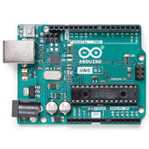
- Arduino UNO R3: This Arduino UNO R3 microcontroller board that will act as the central processing unit for our project. It will run the code that listens for commands and controls the appliances.
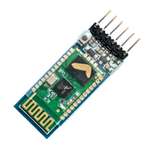
- HC-05 Bluetooth Module: This HC-05 Bluetooth module facilitates wireless communication between the Arduino and your smartphone. It acts as a bridge, converting Bluetooth signals into data the Arduino can understand.
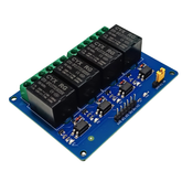
- 4-Channel 5V Relay Module: A relay is an electrically operated switch. This module allows the low-power 5V signal from the Arduino to safely control a high-power 240V appliance, like a light bulb or a fan, without any risk to the microcontroller.
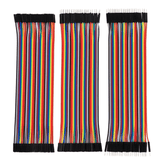
- Jumper Wires: These Jumper Wires are essential for connecting all the components on your breadboard or directly. You will need a mix of male-to-female and female-to-female wires.
- An Appliance: To see your project in action, you will need a simple appliance such as a table lamp or a small fan.
- Smartphone: An Android smartphone is needed to install a Bluetooth control app that will send commands to your Arduino.
Circuit Diagram and Wiring Setup
Properly connecting the components is a critical step. Follow the wiring instructions carefully to ensure your home automation prototype functions correctly and safely. Pay close attention to the connections for the high-voltage appliance.

Safety Warning: This project involves working with high-voltage AC electricity, which can be extremely dangerous. If you are not experienced or comfortable with handling AC wiring, please seek assistance from someone who is.
Always make sure the appliance is unplugged from the wall outlet before making any wiring changes.
Connecting the Modules to the Arduino
1. Relay Module to Arduino:
- Connect the VCC pin on the relay module to the 5V pin on the Arduino.
- Connect the GND pin on the relay module to one of the GND pins on the Arduino.
- Connect the input pins IN1, IN2, IN3, and IN4 on the relay module to the digital pins 7, 6, 5, and 4 on the Arduino, respectively.
2. Bluetooth Module to Arduino:
- Connect the VCC pin on the HC-05 module to the 5V pin on the Arduino.
- Connect the GND pin on the HC-05 module to the GND pin on the Arduino.
- Connect the TXD (Transmit) pin on the HC-05 module to the RX (Receive) pin (Digital Pin 0) on the Arduino.
- Connect the RXD (Receive) pin on the HC-05 module to the TX (Transmit) pin (Digital Pin 1) on the Arduino.
Wiring the Appliance to the Relay
- Take the power cord of your appliance (e.g., a lamp). Identify the two wires inside: Live and Neutral.
- Carefully cut only the Live wire. Do not cut the Neutral wire.
- Strip a small amount of insulation from the two cut ends of the Live wire.
- Connect one end of the cut Live wire to the center terminal of the first relay, which is labeled ‘COM’ (Common).
- Connect the other end of the cut Live wire to the terminal labeled ‘NO’ (Normally Open).
When the relay is activated by the Arduino, it will close the connection between the COM and NO terminals, completing the circuit and turning the appliance on.
While this project focuses on direct control, more advanced versions could incorporate home automation sensors to trigger appliances based on environmental conditions.
Programming the Smart Home Controller (Arduino)
With the hardware assembled, it's time to give our smart home prototype its intelligence. We will upload a set of instructions, known as a sketch, to the Arduino UNO.
This code will tell Arduino how to interpret signals from the Bluetooth module and how to control the relay module in response.
The logic is straightforward: the Arduino will continuously listen for data coming through its serial port, which is connected to the HC-05 Bluetooth module.
When you press a button on the smartphone app, the app sends a specific character (e.g., ‘a’) via Bluetooth. The HC-05 module receives this character and passes it to the Arduino.
The Arduino sketch checks this character and, if it matches a predefined command, it will execute an action, such as pulling a digital pin LOW to activate a relay. This is the essence of smart home automation using Arduino.
Before uploading the code, you must disconnect the RX and TX wires from the Arduino board (pins 0 and 1).
These pins are used for uploading the sketch, and having the Bluetooth module connected can interfere with the process. Once the code is successfully uploaded, you can reconnect the wires.
// Define the pins for the relay channels
int relay1 = 7;
int relay2 = 6;
int relay3 = 5;
int relay4 = 4;

char command; // Variable to store the received command from Bluetooth

void setup() {
  // Start serial communication at 9600 baud rate
  Serial.begin(9600);

  // Set the relay pins as outputs
  pinMode(relay1, OUTPUT);
  pinMode(relay2, OUTPUT);
  pinMode(relay3, OUTPUT);
  pinMode(relay4, OUTPUT);

  // Set the initial state of the relays to OFF (HIGH)
  // Note: Some relay modules are active-LOW, meaning a LOW signal turns them ON.
  digitalWrite(relay1, HIGH);
  digitalWrite(relay2, HIGH);
  digitalWrite(relay3, HIGH);
  digitalWrite(relay4, HIGH);
}

void loop() {
  // Check if data is available to read from the serial port
  if (Serial.available() > 0) {
    // Read the incoming character
    command = Serial.read();

    // Stop all relays before processing the new command
    // This prevents multiple relays from being on at once if not intended
    digitalWrite(relay1, HIGH);
    digitalWrite(relay2, HIGH);
    digitalWrite(relay3, HIGH);
    digitalWrite(relay4, HIGH);

    // Check the received command and control the corresponding relay
    switch (command) {
      case 'a': // Command to turn Relay 1 ON
        digitalWrite(relay1, LOW);
        break;
      case 'b': // Command to turn Relay 1 OFF
        digitalWrite(relay1, HIGH);
        break;
      case 'c': // Command to turn Relay 2 ON
        digitalWrite(relay2, LOW);
        break;
      case 'd': // Command to turn Relay 2 OFF
        digitalWrite(relay2, HIGH);
        break;
      case 'e': // Command to turn Relay 3 ON
        digitalWrite(relay3, LOW);
        break;
      case 'f': // Command to turn Relay 3 OFF
        digitalWrite(relay3, HIGH);
        break;
      case 'g': // Command to turn Relay 4 ON
        digitalWrite(relay4, LOW);
        break;
      case 'h': // Command to turn Relay 4 OFF
        digitalWrite(relay4, HIGH);
        break;
    }
  }
}
Where to Buy IoT and Smart Home Components Online (Robocraze)
Finding the right components is fundamental to success when you build a smart home project. For hobbyists and creators in India, Robocraze is a premier online destination for electronics components.
They offer a comprehensive selection of genuine Arduino boards, sensors, modules, and accessories needed to construct your smart home prototype.
Shopping with Robocraze ensures that you receive high-quality, tested components, which minimizes troubleshooting and compatibility issues.
Their extensive catalog includes everything from the Arduino UNO and HC-05 Bluetooth module to the relay modules and jumper wires mentioned in this guide.
By providing all the necessary parts in one place, Robocraze empowers makers to move from concept to creation seamlessly, supporting the growth of the DIY electronics community.
Conclusion
Congratulations, you have successfully outlined the steps to build a functional smart home prototype! This project is a fantastic entry point into the exciting field of home automation.
You have learned how to wire electronic components, program a microcontroller to respond to wireless commands, and safely control a high-voltage appliance. The skills you have acquired are foundational and can be expanded upon for more complex projects.
Consider upgrading to a Wi-Fi module like the ESP8266 for internet-based control or integrating sensors to create a truly automated system. The world of DIY smart homes is vast, and you have just taken your first, most important step.


