How to Solder Wires and Components on a PCB (Step-by-Step Guide)
Summary
I'm excited to share with you one of the most fundamental skills in electronics - PCB soldering.
As someone who has been working with electronic components for many years, I understand that proper soldering techniques can make the difference between a reliable project and one that fails at the most crucial moment.
In this guide, I'll explain everything you need to know about soldering wires and components on printed circuit boards.
Whether you're just starting out or looking to improve your skills, we'll cover it all in a way that's practical and easy to follow.
This is one of those skills that requires patience and practice, but once you master it, it opens up endless possibilities for your electronic projects.

Introduction to PCB Soldering
PCB soldering is the process of joining electronic components to printed circuit boards using a metal alloy called solder.
This technique creates both mechanical connections and electrical pathways that allow your circuits to function properly. Think of it as the foundation upon which all electronic projects are built.
The soldering process involves heating a metal alloy (typically a mixture of tin and other metals) until it melts and flows between the component leads and the copper pads on your PCB.
When the solder cools and solidifies, it forms a permanent bond that conducts electricity while holding the component securely in place.
What makes PCB soldering particularly important is that it's not just about making connections - it's about making reliable, long-lasting connections that will withstand temperature variations, vibrations, and time.
Poor soldering can lead to intermittent connections, circuit failures, and even safety hazards in some applications.
Modern electronics manufacturing relies heavily on various soldering techniques, from traditional through-hole soldering to advanced surface-mount technology.
Understanding these fundamentals will serve you well whether you're working on hobby projects or professional applications.
Tools and Materials Required for Soldering
Before we dive into the actual soldering process, let's ensure you have all the necessary tools and materials.
Having the right equipment makes a significant difference in achieving professional results.
Essential Tools
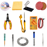
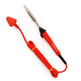
- Soldering Iron: The heart of your soldering setup. I recommend a temperature-controlled iron with adjustable heat settings, typically ranging from 300°C to 400°C. A good soldering iron should have a comfortable grip and replaceable tips.
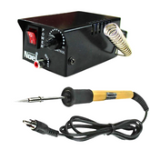
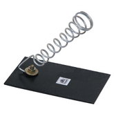
- Soldering Station: For serious work, consider investing in a soldering station that includes temperature control, a stand, and a cleaning sponge. This provides better temperature stability and safety features.
- Solder Wire: Choose the right solder wire for your application. For electronics work, I recommend 60/40 or 63/37 tin-lead solder with a rosin core, typically in 0.6mm to 0.8mm diameter.
- Flux: Additional flux helps improve solder flow and creates better joints. Rosin-based flux is most commonly used for electronics.
Supporting Equipment
- Wire Strippers: Wire strippers are essential for removing insulation without damaging the conductors.
- Flush Cutters: For trimming component leads after soldering.
- Cleaning Supplies: Isopropanol and cleaning wipes for removing flux residue.
- Safety Equipment: Safety glasses and adequate ventilation are crucial for protecting yourself during the soldering process.
Preparing the PCB and Components for Soldering
Proper preparation is important for achieving reliable solder joints. This soldering guide for beginners emphasizes that taking time to prepare your materials properly will save you hours of troubleshooting later.
Cleaning the PCB Surface
Start with a clean PCB surface by removing any dust, fingerprints, or oxidation from the copper pads.
Use isopropanol and a lint-free cloth to clean the areas where you'll be soldering. This ensures optimal solder adhesion and electrical conductivity.
Component Preparation
For through-hole components, ensure the leads are clean and straight. If you're working with wires, strip the insulation to expose about 6-8mm of conductor.
The exposed wire length should be sufficient to make good contact with the pad while allowing room for the solder to flow properly.
PCB Positioning
Secure your PCB in a stable position using a PCB holder or helping hands. The board should be easily accessible from both sides if you're working with through-hole components.
Good positioning prevents movement during soldering, which can create poor joints.
Component Placement
Insert components into their designated positions, ensuring correct orientation for polarized components like LEDs and diodes. For through-hole components, the leads should protrude through the PCB with minimal gaps between the component body and the board surface.
How to Tin Wires and Component Leads Before Soldering
Tinning is a preliminary step that coats wires and component leads with a thin layer of solder.
This technique improves heat transfer and creates stronger, more reliable connections when you perform the final soldering.
Wire Tinning Process
Heat your soldering iron to approximately 350°C and clean the tip with a damp sponge. Strip the wire insulation, exposing about 6-8mm of conductor.
Touch the hot iron tip to the wire while simultaneously applying solder to the joint between the iron and wire.
The solder should flow smoothly along the wire strands, filling the gaps between individual conductors. Move the iron slowly along the wire to ensure even coverage.
Component Lead Preparation
For component leads that appear oxidized or dirty, light tinning can improve connection quality.
Apply the iron tip to the lead while adding a small amount of fresh solder. The goal is a thin, even coating that will facilitate better heat transfer during final soldering.
Benefits of Tinning
Properly tinned wires and leads heat up more quickly during soldering, reducing the time needed to form joints.
This minimizes heat damage to sensitive components and creates more consistent results. Tinned surfaces also resist oxidation, maintaining their solderability over time.
Step-by-Step Guide to Soldering Wires on a PCB
Now let's walk through the complete process of soldering wires to a PCB. This PCB soldering tutorial covers the essential steps for creating reliable connections.
Step 1: Iron Preparation
Heat your soldering iron to the appropriate temperature (typically 350-400°C for electronics work).
Clean the tip with a damp sponge and apply a small amount of fresh solder to the tip. This process, called tinning the iron, improves heat transfer and protects the tip from oxidation.
Step 2: Joint Positioning
Position the tinned wire against the PCB pad where you want to make the connection. The wire should make good physical contact with the pad surface.
If using helping hands, secure both the PCB and the wire in stable positions.
Step 3: Heat Application
Touch the soldering iron tip to both the wire and the PCB pad simultaneously. The iron should make contact with both surfaces to ensure even heating.
Hold this position for 2-3 seconds to allow heat to transfer throughout the joint area.
Step 4: Solder Application
While maintaining the iron position, apply fresh solder to the joint from the opposite side of where the iron is positioned.
The heated surfaces should melt the solder immediately upon contact. Apply enough solder to create a smooth, concave fillet around the wire.
Step 5: Cooling and Inspection
Remove the solder wire first, then lift the iron straight up and away from the joint. Keep the wire and PCB stationary until the solder cools completely (usually 3-5 seconds).
The finished joint should appear smooth, shiny, and have a characteristic volcano or cone shape.
Soldering Through-Hole Components
Through-hole components require a slightly different approach than wire soldering. These soldering techniques are fundamental for assembling traditional PCBs and prototypes.
Component Insertion
Insert the component leads through the appropriate holes in the PCB. The component body should sit flush against the PCB surface, or at the specified height according to your design requirements.
Gently bend the leads outward at approximately 45 degrees to hold the component in place.
Sequential Soldering
Start by soldering one lead to secure the component position. Heat the copper pad and component lead simultaneously while applying fresh solder from the opposite side.
The solder should flow smoothly around the lead and fill the hole completely.
Multiple Pin Components
For components with multiple pins, solder diagonally opposite pins first to secure the component position.
This prevents the component from shifting during the soldering of the remaining pins. Work systematically through all remaining connections, allowing each joint to cool before moving to the next.
Lead Trimming
After all joints have cooled completely, use flush cutters to trim excess component leads.
Cut as close to the solder joint as possible without damaging the connection. Hold the lead being cut to prevent it from flying across your workspace.
Soldering Surface-Mount Components (SMT)
Surface-mount technology presents unique challenges but follows similar principles to through-hole soldering.
These how to solder electronic components techniques require more precision and patience.
Component Positioning
SMT components mount directly onto pads on the PCB surface rather than through holes. Precise positioning is critical because these components are much smaller and their pads are closer together.
Use tweezers to position components and ensure proper alignment before soldering.
Tacking Method
Begin by applying a small amount of solder to one pad of the component footprint. Position the component correctly and heat the pre-tinned pad while holding the component in place.
This creates a temporary connection that holds the component steady while you solder the remaining connections.
Drag Soldering
For components with multiple closely-spaced pins, apply flux generously across all pads. Apply solder to your iron tip and drag it smoothly across all the pins simultaneously.
The flux helps prevent solder bridges between adjacent pins, and proper technique allows the solder to flow to the correct locations.
Bridge Removal
If solder bridges form between pins, use desoldering wick or a clean iron tip to remove excess solder.
Apply flux to the bridged area and touch the wick with a hot iron to absorb the unwanted solder.
Conclusion
Mastering PCB soldering is a journey that requires patience, practice, and attention to detail.
The techniques we've covered here - from basic wire soldering to advanced surface-mount work - form the foundation of virtually all electronic assembly and repair work.
Remember that good soldering techniques are about creating reliable, long-lasting bonds that will serve your projects well for years to come.
Start with simple through-hole components, practice regularly, and gradually work your way up to more challenging surface-mount devices.
The key principles remain consistent regardless of the specific application: clean surfaces, proper heat control, good joint preparation, and steady hands.
With these fundamentals and regular practice, you'll develop the confidence and skill needed to tackle any soldering on circuit board project that comes your way.


