What Is an Inductor in Electronics?
Summary
If you've ever wondered how a radio tunes into a specific station or how a power supply provides a steady, clean flow of electricity, you've encountered the work of an often-overlooked component in the world of electronics.
Alongside resistors and capacitors, there is a third fundamental passive component that is essential to countless devices we use every day.
Imagine a heavy flywheel; it takes effort to get it spinning, and once it's at speed, it resists any attempt to slow it down.
This tendency to oppose change is the perfect analogy for the electronic component we're exploring in this blog post: the inductor.
These tiny powerhouses are found in everything from your smartphone charger to the complex circuitry in your car.
Let's take a closer look at what inductors are, how they are built, and the crucial roles they play in modern technology.

What is an Inductor?
An inductor is a passive electronic component that stores energy in the form of a Magnetic Field whenever electric current flows through it.
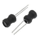
You'll often hear it referred to by its other names, like a choke or, more descriptively, a Coil. This name gives a clue to its structure: an inductor is typically just an insulated wire wound into a coil, sometimes around a central core material.
The defining characteristic of an Inductor is its inductance, which is its inherentent property to oppose any change in the current flowing through it.
Think back to our flywheel analogy. When current starts to flow through the inductor (like pushing the flywheel), the inductor pushes back, resisting the change.
Once the current is steady, the inductor is happy and lets it flow. But if you try to decrease or stop the current (like trying to stop the spinning flywheel), the inductor will release its stored energy to try and keep the current flowing.
This phenomenon is a direct result of Electromagnetic Induction. As current flows through the coil, it generates a magnetic field; if that current changes, the magnetic field also changes, which in turn induces a voltage that works against the initial change in current.
This property is measured in a unit called the henry (H), named after the American scientist Joseph Henry.
Constructing an Inductor

The construction of an inductor is deceptively simple, yet the specific design choices have a massive impact on its performance. The two primary components are the coil and the core.
The Coil itself is almost always made of a highly conductive material, most commonly insulated copper wire. The wire is wound into a series of loops.
The number of loops, or turns, is a critical factor: the more turns the wire has, the higher the inductance will be because a stronger magnetic field can be generated.
The second component is the core, which is the material that the coil is wrapped around. The core material's job is to concentrate the magnetic field lines, which significantly increases the inductance. Cores can be made from various materials:
- Ferromagnetic Cores (like Iron): These materials, such as laminated iron or soft ferrites, have a high magnetic permeability. This means they are excellent at concentrating magnetic fields, allowing for very high inductance values in a compact size. They are often used in power supplies and audio-frequency filters.
- Air Cores: In some inductors, the coil is simply wound around a non-magnetic material like plastic, ceramic, or even just air. Because air has a low permeability, these inductors have much lower inductance values. However, their advantage is that they don't suffer from the energy losses that can occur in core materials at very high frequencies, making them ideal for radio circuits and other high-frequency applications.
The final construction is then packaged, sometimes in a shielded casing to prevent its magnetic field from interfering with other components in a circuit.
Types of Inductors

Not all inductors are created equal. Depending on the application, engineers will choose from a variety of Inductor Types designed for specific purposes.
While there are many specialized versions, most fall into a few main categories based on their core material and function.
Iron Core Inductor
- As the name suggests, these use a solid or laminated iron core. They boast high power handling and high inductance, making them staples in audio equipment and low-frequency power filters. Their downside is a limited capacity to function effectively at high frequencies due to energy losses within the core.
Ferrite Core Inductor
- Ferrite is a ceramic-like material made from iron oxides mixed with other metallic elements. It offers high permeability like iron but with much better high-frequency performance. This makes ferrite core inductors incredibly versatile, appearing in everything from switching power supplies to noise filters on computer cables. They are further divided into 'soft' ferrites, which are used for standard inductors, and 'hard' ferrites, which are used to make permanent magnets.
Air Core Inductor
- These are designed for situations where low inductance is needed but signal purity is paramount. With no magnetic core to cause energy loss, they are highly efficient at high frequencies. You will commonly find them in radio frequency tuning circuits, like the ones that help a radio select a specific station.
Functions of an Inductor
An inductor's ability to resist changes in current gives it two primary functions that are fundamental to circuit design: controlling signals and Energy Storage.
First, inductors are masters of signal control. Because an inductor’s opposition to current flow (its impedance) increases with frequency, it can be used to selectively block high-frequency signals while letting low-frequency or DC signals pass.
This is the core principle behind its use as a filter. When paired with capacitors, which have the opposite characteristic (they pass high frequencies more easily), they can form incredibly precise LC filters.
These filters are the reason a radio can tune into one station while rejecting all others, and they are crucial for separating different parts of a complex signal.
The second major function is Energy Storage. When current flows through an inductor, the energy doesn't just disappear; it's converted and stored within the Magnetic Field surrounding the coil.
This energy can be released back into the circuit when the current flow is interrupted. This capability is the heart of technologies like switching power supplies (found in nearly all modern electronics), which efficiently convert voltages by repeatedly storing energy in an inductor and then releasing it at a different voltage level.
Inductors in Series and Parallel

Just like resistors, inductors can be connected in a circuit in two basic ways: series or parallel.
The rules for calculating the total inductance are straightforward and are the opposite of how capacitors are calculated.
When inductors are connected in series (end-to-end in a single line), their individual inductances simply add up.
The current flowing through each inductor is the same, and the total inductance (LT) is the sum of the individual ones.
LT = L1 + L2 + L3 + ...
When inductors are connected in parallel (where the terminals of all inductors are connected to the same two points), the total inductance is less than that of the smallest individual inductor.
In this configuration, the voltage across each inductor is the same, but the current splits among them. The formula for the total inductance is the sum of the reciprocals.
1/LT = 1/L1 + 1/L2 + 1/L3 + ...
These principles allow engineers to combine standard-value inductors to achieve a precise inductance needed for a specific circuit function.
Energy Storage in an Inductor
We’ve mentioned that an inductor stores energy, but how does it actually accomplish this? The process is a direct application of the principle of Electromagnetic Induction.
When a voltage source is connected, it does work to push current through the coil against the inductor's initial opposition.
This work isn't lost as heat (as it would be in a pure resistor); instead, it is converted into potential energy stored in the surrounding Magnetic Field.
The amount of energy an inductor can store is determined by its inductance (L) and the square of the current (I) flowing through it. The formula is given by:
E = ½ LI²
This equation shows that a higher inductance or a higher current will result in more stored energy. This stored energy is what gives an inductor its "momentum." When the external current supply is cut off, the magnetic field begins to collapse.
As it collapses, it induces a voltage in the coil that tries to keep the current flowing, effectively releasing the stored energy back into the circuit.
This is the principle behind ignition coils in cars, which create a high-voltage spark by rapidly interrupting the current flowing through a large inductor.
Inductor Reactance and Impedance
The term "resistance" is often used to describe opposition to current flow, but in AC circuits, the situation is more complex.
For an Inductor, its opposition to alternating current is called inductive reactance (denoted as XL).
Unlike simple resistance, inductive reactance is not fixed; it depends entirely on the frequency (f) of the AC signal.
The formula for inductive reactance is:
XL = 2πfL
This formula tells us something very important:
- For a DC signal (where f = 0), the reactance is zero. An inductor acts like a simple piece of wire to steady DC.
- As the frequency of the AC signal increases, the reactance increases proportionally. An inductor presents a much greater opposition to high-frequency AC than to low-frequency AC.
Impedance (Z) is the total opposition to current flow in an AC circuit, which includes both the reactance of inductors and capacitors and the simple resistance of components.
For an inductor, impedance is largely determined by its reactance and is a key factor in designing filters and signal-shaping circuits.
Difference Between an Inductor and a Capacitor
Inductors and capacitors are often referred to as the "yin and yang" of passive components because their behaviors are complementary opposites. Understanding their differences is key to understanding electronics.
| Feature | Inductor | Capacitor |
|---|---|---|
| Energy Storage | Stores energy in a Magnetic Field | Stores energy in an Electric Field |
| Response to DC | Acts as a short circuit (wire) once the current is steady | Acts as an open circuit (break) once fully charged |
| Response to AC | Opposition (reactance) increases with frequency | Opposition (reactance) decreases with frequency |
| Primary Function | Resists changes in current | Resists changes in voltage |
| Current/Voltage Phase | Current lags voltage by 90° | Current leads voltage by 90° |
In essence, while both store energy, an Inductor does so by creating a magnetic field in response to current, while a capacitor does so by accumulating an electrical charge in response to voltage.
This fundamental difference is why they are often used together to create resonant circuits that can oscillate or tune to specific frequencies.
Conclusion
From the simple act of filtering noise in a power adapter to the complex task of tuning a radio signal, the inductor is an indispensable component in the toolkit of an electronics engineer.
Though its construction is little more than a coil of wire, its ability to store energy in a magnetic field and resist changes in current gives it a unique and powerful set of capabilities.
It acts as a gatekeeper for frequencies, a temporary energy reservoir, and a crucial partner to the capacitor in creating resonant circuits.
The next time you power on a device, take a moment to appreciate the silent, invisible work being done by these tiny coils, masterfully managing the flow of electrons to make our technology possible.


