


LED Interfacing with Arduino
In this blog, we will see LED Blinking using Arduino.
What is an LED?
A light-emitting diode (LED) is a semiconductor component that emits light by allowing an electric current to pass through it.
The light is produced as a result of electrons and holes recombining due to the current, which releases energy in the form of light.
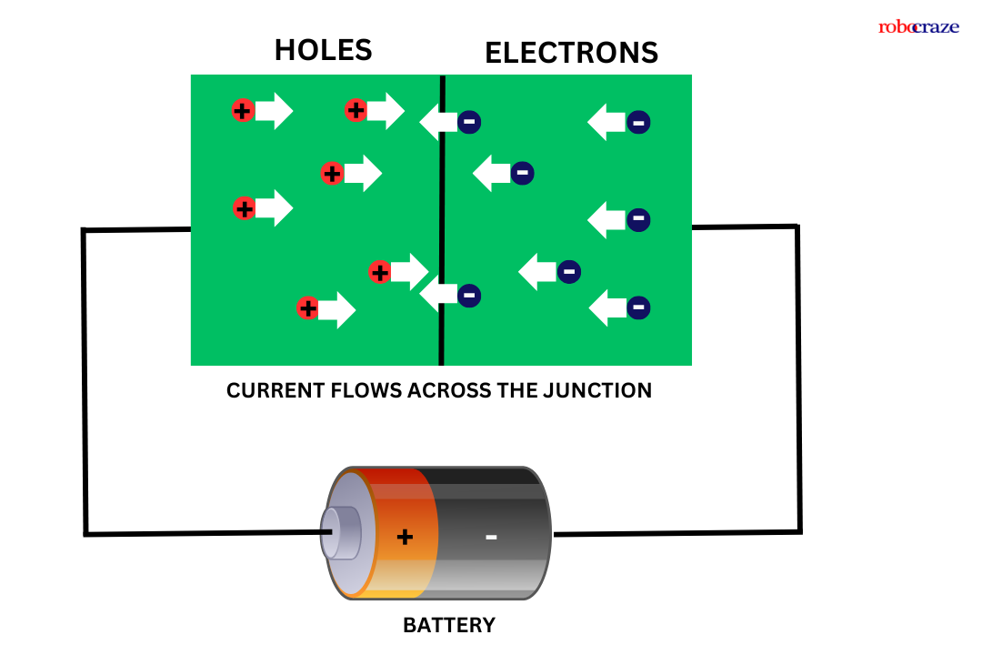
LEDs are designed with a highly doped p-n junction that permits the flow of current in one direction while hindering it in the opposite direction.
The color of the light is determined by the semiconductor material used and its processing method. Every material releases light at a distinct wavelength, leading to a variety of colors.
Various semiconductor materials are employed in light-emitting diodes (LEDs), with each possessing a unique ability to produce a specific shade of light.
High-brightness blue, green, and ultraviolet LEDs are achieved through the utilization of indium gallium nitride (InGaN) as the primary material.
When vibrant yellows, oranges, and reds are desired, aluminum gallium indium phosphide (AlGaInP) is the preferred material.
For red and infrared LEDs, aluminum gallium arsenide (AlGaAs) is commonly employed.
Lastly, gallium phosphide (GaP) is renowned for its capability to produce yellow and green LEDs. The utilization of these diverse materials enables LED lighting to offer a broad spectrum of colors and varying levels of brightness.
Pinout of LED:

The anode and cathode are the two terminals found on LEDs. The positive terminal is referred to as the anode, and the negative terminal as the cathode.
Normally, one can tell which is the cathode and which is the anode by measuring the length of each terminal. The longer terminal is called the anode.
Another method is to check the outside housing of the LED for a flat edge. The anode is the terminal next to this flat edge, while the cathode is the terminal across from the anode.
Hardware Required for interfacing LED with Arduino:
- Arduino (You can use any Arduino board for this project) - 1
- LED - 1 (You can use LED of any color)
- Resistor 330ohm - 1
- Jumper wires - As required
- Breadboard - 1
read more : What is Arduino Nano
Also, read our blog on Buzzer Arduino detailing step by step guide about how to use the buzzer with your Arduino board.
Connection of LED with Arduino:

|
GPIO 3 of Arduino |
Anode pin of LED via 220ohm resistor |
|
GND pin of Arduino |
Cathode pin of the LED |
How to interface LED with an Arduino:
To blink the LED using Arduino, here are the simple steps
First, we need the above-mentioned components and connections to be made as per the circuit diagram below.
Next, we have to program our Arduino. For programming our Arduino to blink an LED, we need Arduino IDE to be installed on our PC. You can download and install Arduino IDE suitable for your computer OS from arduino.cc
Once, the Arduino IDE is installed on your PC, we have to write a code to blink an LED in the interval of one second. Below is the code for blinking LED using Arduino.
read more : Arduino Pin Configuration
Code for LED Blinking:
#define led_pin 3


void setup()

{

 pinMode(led_pin, OUTPUT);

}


void loop()

{

 digitalWrite(led_pin, HIGH);

 delay(1000);

 digitalWrite(led_pin, LOW);

 delay(1000);

}
Explanation:
#define led_pin 3
#define led_pin 3 : First, we have declared a pin name and pin number to which we are going to connect the LED using #define preprocessor constant. We are assigning GPIO 3 pin of Arduino to connect LED and given a name to that pin as “led_pin”.
void setup()
{
pinMode(led_pin, OUTPUT);
}
void setup() : This function executes only once in our program. In this function, we have called a function called “pinMode(led_pin, OUTPUT);”.
The pinMode function is used to tell Arduino, that the connected peripheral is either input or output peripheral.
In this function, we are passing the “led_pin” as pin name and “OUTPUT” as type.
void loop()
{
digitalWrite(led_pin, HIGH);
delay(1000);
digitalWrite(led_pin, LOW);
delay(1000);
}
void loop() : This function executes infinitely in our program. In this function, we have called a function “digitalWrite();” in this function, we pass two arguments. Such as the pin name to which the LED is connected and the state of the pin.
“digitalWrite(led_pin, HIGH);” makes the led_pin as HIGH means provides 5V at GPIO pin 3. “digitalWrite(led_pin, LOW);” makes the voltage on the GPIO pin 3 to 0V.
In between these two functions, we have used a “delay();” function is used to pause the microcontroller for some time during the execution.
In this program, we are passing “1000” as an argument to the delay(); function. Which gives a delay of 1000 milliseconds. i.e., 1 second.
read more : Exploring LCD Displays and Arduino UNO
Conclusion:
An easy and entertaining method to begin learning about hardware programming is to connect an LED to an Arduino. Gaining the confidence to start on fascinating projects that can illuminate your surrounds will come from knowing how to connect the pins, interact with the LED, and write some basic code.
After reading this article's advice, you should be able to connect an LED to an Arduino with ease for LED Blinking. With this knowledge, you may work on more intricate hardware projects and let your creativity run wild. So take out your Arduino board and LED, and start making your imaginative thoughts come to life!
If you appreciate our work don't forget to share this post and leave your opinion in the comment box.
Please do check out other blog posts about Interfacing ACS712 with Arduino , Arduino Interfacing with Ultrasonic Sensor , Interfacing GSM Module with Arduino , Interfacing MAX30100 Pulse Oximeter with Arduino , IR Sensor Interfacing with Arduino , How to connect ZMPT101B to Arduino and How to use Buzzer with Arduino.
Make sure you check out our wide range of products and collections (we offer some exciting deals!)