


Summary
This tutorial is best suited for those who want to learn how to connect an LED to an Arduino. It will walk you through the LED's pinout, the necessary hardware, and connecting it to an Arduino.
The web page also offers a comprehensive lesson on creating code for the project. No matter how much or little experience you have with Arduino, you will find informative articles and helpful tips.
Are you ready to dive straight in? Now is the time to start your LED project and see what you can create!
In this blog, we will see LED Blinking using Arduino.
What is an LED?
A light-emitting diode (LED) is a semiconductor component that emits light by allowing an electric current to pass through it.
The light is produced as a result of electrons and holes recombining due to the current, which releases energy in the form of light.
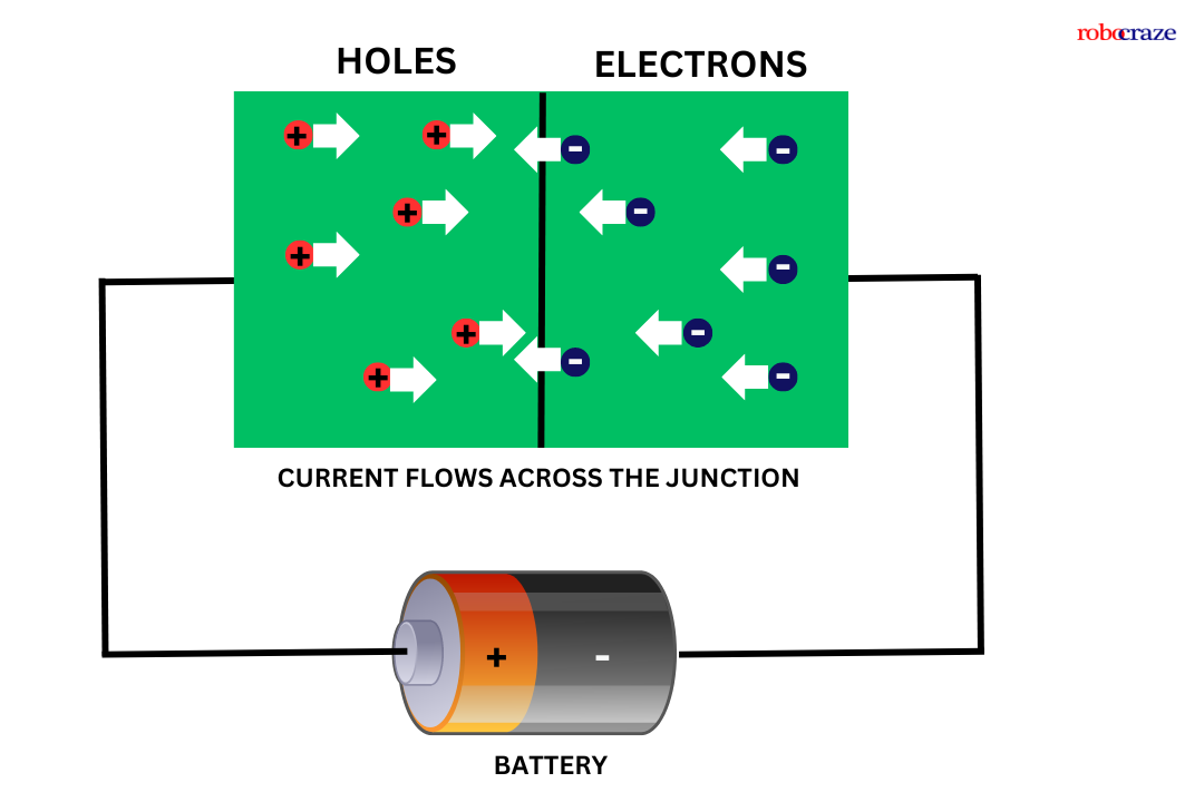
LEDs are designed with a highly doped p-n junction that permits the flow of current in one direction while hindering it in the opposite direction.
The color of the light is determined by the semiconductor material used and its processing method. Every material releases light at a distinct wavelength, leading to a variety of colors.
Various semiconductor materials are employed in light-emitting diodes (LEDs), with each possessing a unique ability to produce a specific shade of light.
High-brightness blue, green, and ultraviolet LEDs are achieved through the utilization of indium gallium nitride (InGaN) as the primary material.
When vibrant yellows, oranges, and reds are desired, aluminum gallium indium phosphide (AlGaInP) is the preferred material.
For red and infrared LEDs, aluminum gallium arsenide (AlGaAs) is commonly employed.
Lastly, gallium phosphide (GaP) is renowned for its capability to produce yellow and green LEDs. The utilization of these diverse materials enables LED lighting to offer a broad spectrum of colors and varying levels of brightness.
Components and Supplies


5mm Green Led (Pack of 10)
- Rs 15/-
- Rs 15/-
-
Rs 19/-


330 Ohm Resistor - (Pack of 10)
- Rs 13/-
- Rs 13/-
-
Rs 19/-


Jumper Wire Set - M2M, M2F, F2F (40 pcs each)
- Rs 139/-
- Rs 139/-
-
Rs 169/-


Arduino Uno R3 Original
- Rs 2,619/-
- Rs 2,619/-
-
Rs 2,649/-
Why Resistor is Important
When connecting an LED to an Arduino, a resistor is a critical component that protects both the LED and the microcontroller. LEDs are designed to operate within a specific current range, and connecting them directly to a power source can allow excessive current to flow through the circuit.
A resistor limits this current to a safe level, preventing the LED from overheating or burning out. In most Arduino projects, resistors between 220Ω and 330Ω are commonly used for LED circuits.
If you are following an led interfacing with arduino project, always place the resistor in series with the LED. This simple addition improves reliability and extends the lifespan of your components. Whether you're building a basic led arduino blinking project or a more advanced lighting system, proper current limiting is essential for safe circuit operation.
Pinout of LED:

The anode and cathode are the two terminals found on LEDs. The positive terminal is referred to as the anode, and the negative terminal as the cathode.
Normally, one can tell which is the cathode and which is the anode by measuring the length of each terminal. The longer terminal is called the anode.
Another method is to check the outside housing of the LED for a flat edge. The anode is the terminal next to this flat edge, while the cathode is the terminal across from the anode.
Hardware Required for interfacing LED with Arduino:
- Arduino (You can use any Arduino board for this project) - 1
- LED - 1 (You can use LED of any color)
- Resistor 330ohm - 1
- Jumper wires - As required
- Breadboard - 1
read more : What is Arduino Nano
Also, read our blog on Buzzer Arduino detailing step by step guide about how to use the buzzer with your Arduino board.
Connection of LED with Arduino:

|
GPIO 3 of Arduino |
Anode pin of LED via 220ohm resistor |
|
GND pin of Arduino |
Cathode pin of the LED |
How to interface LED with an Arduino:
To blink the LED using Arduino, here are the simple steps
First, we need the above-mentioned components and connections to be made as per the circuit diagram below.
Next, we have to program our Arduino. For programming our Arduino to blink an LED, we need Arduino IDE to be installed on our PC. You can download and install Arduino IDE suitable for your computer OS from arduino.cc
Once, the Arduino IDE is installed on your PC, we have to write a code to blink an LED in the interval of one second. Below is the code for blinking LED using Arduino.
read more : Arduino Pin Configuration
Code for LED Blinking:
#define led_pin 3


void setup()

{

 pinMode(led_pin, OUTPUT);

}


void loop()

{

 digitalWrite(led_pin, HIGH);

 delay(1000);

 digitalWrite(led_pin, LOW);

 delay(1000);

}
Explanation:
#define led_pin 3
#define led_pin 3 : First, we have declared a pin name and pin number to which we are going to connect the LED using #define preprocessor constant. We are assigning GPIO 3 pin of Arduino to connect LED and given a name to that pin as “led_pin”.
void setup()
{
pinMode(led_pin, OUTPUT);
}
void setup() : This function executes only once in our program. In this function, we have called a function called “pinMode(led_pin, OUTPUT);”.
The pinMode function is used to tell Arduino, that the connected peripheral is either input or output peripheral.
In this function, we are passing the “led_pin” as pin name and “OUTPUT” as type.
void loop()
{
digitalWrite(led_pin, HIGH);
delay(1000);
digitalWrite(led_pin, LOW);
delay(1000);
}
void loop() : This function executes infinitely in our program. In this function, we have called a function “digitalWrite();” in this function, we pass two arguments. Such as the pin name to which the LED is connected and the state of the pin.
“digitalWrite(led_pin, HIGH);” makes the led_pin as HIGH means provides 5V at GPIO pin 3. “digitalWrite(led_pin, LOW);” makes the voltage on the GPIO pin 3 to 0V.
In between these two functions, we have used a “delay();” function is used to pause the microcontroller for some time during the execution.
In this program, we are passing “1000” as an argument to the delay(); function. Which gives a delay of 1000 milliseconds. i.e., 1 second.
read more : Exploring LCD Displays and Arduino UNO
Troubleshooting
If your LED does not blink as expected, there are several common issues worth checking.
LED Not Turning On
- Verify that the anode and cathode are connected correctly.
- Check whether the resistor and LED are properly seated on the breadboard.
- Ensure the correct Arduino pin number is defined in the code.
LED Always ON
- Confirm that the sketch contains both HIGH and LOW states.
- Check for wiring mistakes that bypass the Arduino output pin.
Upload Errors
- Verify that the correct board and COM port are selected in the Arduino IDE.
- Reconnect the USB cable and try uploading again.
Dim LED Output
- Use an appropriate resistor value.
- Ensure the Arduino board is receiving stable power.
Reviewing the circuit against the led interfacing diagram can quickly help identify wiring errors and restore proper functionality.
Beginner Project Ideas
Once you have successfully blinked an LED, you can explore more practical Arduino projects that build upon the same concepts.
Traffic Light Simulator
Use red, yellow, and green LEDs to simulate a traffic signal sequence and learn timing control.
LED Pattern Generator
Create different blinking patterns, running lights, and visual effects using multiple LEDs.
Reaction Timer Game
Measure a user's reaction speed by combining LEDs with push buttons and simple Arduino programming.
Smart Notification Indicator
Use LEDs to display system status, alerts, or sensor conditions in IoT projects.
LED and Buzzer Alarm
A great next step is interfacing led and buzzer with arduino to create a simple alert system. The LED provides visual feedback while the buzzer generates an audible warning when a specific condition is met.
These beginner-friendly projects help strengthen your understanding of Arduino programming, digital outputs, and electronic circuit design while preparing you for more advanced hardware projects.
Conclusion:
An easy and entertaining method to begin learning about hardware programming is to connect an LED to an Arduino. Gaining the confidence to start on fascinating projects that can illuminate your surrounds will come from knowing how to connect the pins, interact with the LED, and write some basic code.
After reading this article's advice, you should be able to connect an LED to an Arduino with ease for LED Blinking. With this knowledge, you may work on more intricate hardware projects and let your creativity run wild. So take out your Arduino board and LED, and start making your imaginative thoughts come to life!
If you appreciate our work don't forget to share this post and leave your opinion in the comment box.
Please do check out other blog posts about Interfacing ACS712 with Arduino , Arduino Interfacing with Ultrasonic Sensor , Interfacing GSM Module with Arduino , Interfacing MAX30100 Pulse Oximeter with Arduino , IR Sensor Interfacing with Arduino , How to connect ZMPT101B to Arduino and How to use Buzzer with Arduino.
Make sure you check out our wide range of products and collections (we offer some exciting deals!)
Excerpt
Frequently Asked Questions
1. What is interfacing LED with Arduino?
Interfacing LED with Arduino means, connecting the LED to a GPIO pin of Arduino and controlling it by writing a program.
2. Can LED be connected directly to Arduino?
No, we should not connect LED directly to Arduino. As the GPIO pins of Arduino provide 5V on a HIGH state, due to overvoltage, the LED might get damaged. A resistor in series with the LED pin has to be used to avoid over-voltage damage.
3. How can you make an LED blink using Arduino Uno?
An LED can be made to blink at an interval of a given time. The code in the above blog can be used to blink an LED using Arduino UNO.
4. Do LEDs need resistors on Arduino?
Yes, LEDs need resistors while using with Arduino to avoid over-voltage damage.
5. How do you connect an LED to an Arduino board?
To connect an LED to an Arduino, connect the longer leg (anode) to a digital pin and the shorter leg (cathode) to the ground (GND). You can use a resistor in series to limit current and protect the LED. Typically, a 220Ω or 330Ω resistor works well for most standard LEDs.
6. What resistor should you use with an LED on Arduino?
The resistor value depends on the LED's specifications and the voltage from the Arduino. A common choice is 220Ω or 330Ω, which effectively limits current while allowing the LED to shine brightly. Always calculate resistor values using Ohm's law for precise results.
7. How do you make an LED blink using Arduino code?
To make an LED blink, use the `digitalWrite()` and `delay()` functions in your Arduino code. Set the pin to HIGH, wait for 1000 milliseconds (1 second), then set it to LOW and wait again. This creates a simple blink effect. Repeat this in a loop for continuous blinking.
8. Can you control LED brightness with Arduino PWM?
Yes, you can control LED brightness using PWM (Pulse Width Modulation) on Arduino. By using the `analogWrite()` function, you can set values from 0 (off) to 255 (full brightness). This allows for smooth dimming and brightening effects, enhancing your projects.
9. How many LEDs can a single Arduino pin drive safely?
A single Arduino pin can safely drive approximately 20-30 mA of current. Therefore, you can typically connect one LED per pin for optimal safety. If you require more LEDs, consider using transistors or LED drivers to manage the load safely.
10. What happens if an LED is connected without a resistor?
If an LED is connected without a resistor, it may draw excessive current, leading to overheating and premature failure. The LED can burn out almost instantly, potentially damaging the Arduino pin it’s connected to. Always use a resistor to limit current.
11. Can you wire multiple LEDs in series or parallel with Arduino?
You can wire multiple LEDs in series, but the total voltage drop must remain within the Arduino's output limits. For parallel wiring, use a separate resistor for each LED to ensure equal current distribution. Always consider the combined current when connecting multiple LEDs.
12. How do you choose the correct pin for the LED on Arduino?
Select a digital pin on the Arduino that supports PWM for brightness control or a standard digital pin for simple on/off control. Common pins include 2-13 for digital output. Always check your project’s specific requirements and pin availability.
13. What’s the difference between an RGB LED and a simple LED with Arduino?
An RGB LED contains red, green, and blue light elements in one package, allowing you to mix colors by adjusting brightness through PWM. A simple LED emits one color. With RGB LEDs, you can create a wide range of colors by controlling each element individually with Arduino.
14. How do you troubleshoot a non-blinking LED with Arduino?
If your LED isn't blinking, first check the wiring and ensure that the anode and cathode are correctly connected. Verify that the code is uploaded correctly and that the pin number matches. If everything seems fine, test with another LED to rule out component failure.