


Summary
Are you ready to advance your do-it-yourself projects? Consider using an Arduino to build your pulse oximeter.
The first step is to familiarize yourself with the MAX30100 sensor module, which is easier than you may assume.
In this educational blog piece, we'll go over the MAX30100 sensor's foundations. This wonderful gizmo detects both blood oxygen levels and heart rate.
You'll learn how to connect it to an Arduino board so you can start creating your own personalized pulse oximeter.
Irrespective of your familiarity with Arduino, this blog will surely provide you with valuable insights into this intriguing project.
What is the MAX30100 sensor?
MAX30100 sensor is a device that is used to monitor the heart rate and it is also used as a pulse oximeter.

The Pulse oximeter consists of Light-emitting diodes and an IR sensor. And signal processing unit to improve the quality of the output signal.
It works on the input voltage of 1.8V to 3.3V.
Components and Supplies


MAX30102 Pulse Oximeter Heart Rate Sensor Module
- Rs 189/-
- Rs 189/-
-
Rs 209/-


Arduino Uno R3 Original
- Rs 2,619/-
- Rs 2,619/-
-
Rs 2,649/-
Working of MAX30100 pulse oximeter sensor:
Whenever we breathe in oxygen, the oxygen enters our lungs and passes into our blood. The blood carries oxygen to various organs of our body.
Blood carries oxygen to our body, using hemoglobin. During a pulse oximetry reading, a small clam-like device is attached to our finger, earlobe, or toe.
A small beam of light is passed through the finger. This light passes the finger and is used to measure the content of oxygenated or deoxygenated blood.
The sensor has two light-emitting diodes and one photodiode. The LEDs are used to emit the light and the photodiode is used to detect and measure the intensity of the received light.
In MAX30100 one LED emits monochromatic light and the other LED emits infrared light.

The MAX30100 pulse oximeter can measure both the heart pulse rate and the oxygen level in the blood.
The red light that the red LED emits is used to measure the pulse rate. And for measuring the oxygen level, both the LEDs are used.

When the heart pumps the blood, the oxygenated blood is increased in the body. And when the heart relaxes the volume of the oxygenated blood is decreased in the body.
As a result, the time variation in the change of the volume of the oxygenated blood, the pulse rate are calculated. (One variation = one pump of the heart). This whole change in the light is detected and measured by the photodiode.
The oxygen content is measured by using both the Light-emitting diodes. The oxygenated blood in our body absorbs more infrared light and allows red light to pass through it.
And the deoxygenated blood absorbs more red light and allows infrared light to pass through it. The photodiode in the MAX30100 sensor is used to measure the change in the intensity of the light.
Using this photodiode, the intensity of the light which is passed into the finger and the through the blood is measured by the photodiode and passes the signal to the analog to digital converter and gives the output data in form of I2c serial communication protocol.
And using a microcontroller the pulse rate and the blood oxygen measurement are monitored.
read more : How 433MHz RF Module Works & Interfacing With Arduino
MAX30100 Pulse oximeter Pin Diagram
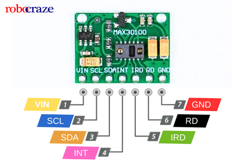
- VIN: This pin is used to turn on the sensor. You may supply either 3.3V or 5V from your Arduino.
- SCL: This is the I2C clock line. Make sure it is connected to the right clock pin on the Arduino.
- SDA: This is where the I2C data pin is situated. It is critical to ensure that the Arduino's I2C data pin and data line are properly connected.
- INT: If the sensor detects a pulse, the INT pin may be activated. It remains high most of the time, but in the event of an interruption, it is dragged down low and remains there until it is cleared.
- IRD: This pin activates the IR LED for heart rate and SpO2 monitoring. If you don't want to operate the IR LED yourself, simply leave it disconnected.
- RD: This pin is identical to the IRD pin, but it controls the red LED. Again, if you are not directly controlling the red LED, you may leave it unattached.
- GND: This is your ground pin; connect it to the Arduino's ground.
Technical Specifications:
| Working voltage | 1.8 ~ 5.5V |
| Shutdown Current | 0.7µA |
| Power supply | 3.3V to 5.5V |
| Current draw | ~600μA (during measurements) |
| Red LED Wavelength | 660nm |
| IR LED Wavelength | 880nm |
| Temperature Range | -40˚C to +85˚C |
| Temperature Accuracy | ±1˚C |
read more: Arduino Sensor types and Applications
How to interface MAX30100 Pulse oximeter with Arduino?
As we know that the MAX30100 Pulse oximeter sensor works on the I2C communication protocol, we have to find out the I2C pins of our Arduino.
In the case of Arduino UNO, A4 and A5 will be the I2C pins. The A4 and A5 are SDA and SCL respectively of the Arduino UNO.

The connection has to be made as shown in the below diagram. If you are using Arduino UNO.
|
Arduino UNO Side |
MAX30100 Side |
|
5V |
VIN |
|
GND |
GND |
|
A4 |
SDA |
|
A5 |
SCL |
read more : Difference Between Arduino and Raspberry Pi
Code:
The below code is used to display the Pulse and the oxygen reading.
#include

#include "MAX30100_PulseOximeter.h"


#define REPORTING_PERIOD_MS     1000

// Create a PulseOximeter object

PulseOximeter pox;

// Time at which the last beat occurred

uint32_t tsLastReport = 0;

// Callback routine is executed when a pulse is detected

void onBeatDetected() {

   Serial.println("Beat!");

}

void setup() {

   Serial.begin(9600);

   Serial.print("Initializing pulse oximeter..");

   // Initialize sensor

   if (!pox.begin()) {

       Serial.println("FAILED");

       for(;;);

   } else {

       Serial.println("SUCCESS");

   }

   // Configure sensor to use 7.6mA for LED drive

   pox.setIRLedCurrent(MAX30100_LED_CURR_7_6MA);

   // Register a callback routine

   pox.setOnBeatDetectedCallback(onBeatDetected);

}

void loop() {

   // Read from the sensor

   Pox update();

   // Grab the updated heart rate and SpO2 levels

   if (millis() - tsLastReport > REPORTING_PERIOD_MS) {

       Serial.print("Heart rate:");

       Serial.print(pox.getHeartRate());

       Serial.print("bpm / SpO2:");

       Serial.print(pox.getSpO2());

       Serial.println("%");

       tsLastReport = millis();

   }

}
Explanation:
Let’s start at the top of the example. Two libraries viz. MAX30100_PulseOximeter.h and Wire.h are included, a constant called REPORTING_PERIOD_MS is defined to delay the measurements, PulseOximeter object is created and a variable called tsLastReport is created to store the time at which the last beat occurred.
#include <Wire.h>
#include "MAX30100_PulseOximeter.h"
#define REPORTING_PERIOD_MS 1000
PulseOximeter pox;
uint32_t tsLastReport = 0;
Next, a callback routine is defined which is executed when a pulse is detected. You can write some interesting code in it, for example, to watch the built-in LED blink with your heartbeat!
void onBeatDetected() {
Serial.println("Beat!");
}
Next let’s look at the setup. There are three functions to point out. First, the pox.begin() function call makes sure that we can communicate with the sensor. begin() function returns 1 on success (or 0 if it fails). It also configures the MAX30100 to begin collecting data.
if (!pox.begin()) {
Serial.println("FAILED");
for(;;);
} else {
Serial.println("SUCCESS");
}
Secondly and equally as important the setIRLedCurrent() function sets the current through the IR LED. The following line sets the current of 7.6mA through the IR LED.
pox.setIRLedCurrent(MAX30100_LED_CURR_7_6MA);
By default the library sets the IR LED current to 50mA which can sometimes cause problems like the LED not turning on or getting the Initializing pulse oximeter.
FAILED message on the serial monitor. In that case, set the LED current to a lower value. Here are the other possible values you can use on the setIRLedCurrent() function.
- MAX30100_LED_CURR_0MA
- MAX30100_LED_CURR_4_4MA
- MAX30100_LED_CURR_7_6MA
- MAX30100_LED_CURR_11MA
- MAX30100_LED_CURR_14_2MA
- MAX30100_LED_CURR_17_4MA
- MAX30100_LED_CURR_20_8MA
- MAX30100_LED_CURR_24MA
- MAX30100_LED_CURR_27_1MA
- MAX30100_LED_CURR_30_6MA
- MAX30100_LED_CURR_33_8MA
- MAXlearnedLED_CURR_37MA
- MAX30100_LED_CURR_40_2MA
- MAX30100_LED_CURR_43_6MA
- MAX30100_LED_CURR_46_8MA
- MAX30100_LED_CURR_50MA
Remember! The higher the current, the brighter the LED and the deeper it reaches your skin. So, you can play with it while you figure it out.
Finally, setOnBeatDetectedCallback() registers callback’s the function.
pox.setOnDetectedCallback(onBeatDetected);
In the main loop, the biometric data is collected from the MAX30100 sensor with the update() function.
It pulls data in from sensor FIFO. (FIFO: The buffer that stores data samples from the sensor. The FIFO has a 16-sample memory bank, which means it can hold up to 16 SpO2 and heart rate samples)
pox.update();
We then print the biometric data on the serial monitor once every second (REPORTING_PERIOD_MS is set to 1000; change it as per your requirement). For this we use millis() instead of delay(). Since delay() pauses the entire code, we cannot get the updated measurement.
if (millis() - tsLastReport > REPORTING_PERIOD_MS) {
Serial.print("Heart rate:");
Serial.print(pox.getHeartRate());
Serial.print("bpm / SpO2:");
Serial.print(pox.getSpO2());
Serial.println("%");
tsLastReport = millis();
}
Serial Monitor:

read more : Top 10 Arduino Projects to Get Started With
Also, read our blog on Arduino IR sensor explaining the required hardware and Arduino code for interfacing Arduino with IR sensorConclusion:
In this blog article, we looked at the MAX30100 pulse oximeter sensor and its interoperability with the Arduino microcontroller board. With the proper configuration and code, you can simply measure blood oxygen levels and heart rate.
So, why not delve into this intriguing project? Grab your MAX30100 sensor and start playing with all of its capabilities. The path to understanding your health data begins here, so be ready for your next DIY adventure!
If you appreciate our work don't forget to share this post and leave your opinion in the comment box.
Please do check out other blog posts about Interfacing ACS712 with Arduino , Arduino Interfacing with Ultrasonic Sensor , LED Interfacing with Arduino , Interfacing GSM Module with Arduino , IR Sensor Interfacing with Arduino , How to connect ZMPT101B to Arduino and How to use Buzzer with Arduino.
Make sure you check out our wide range of products and collections (we offer some exciting deals!)
Excerpt
Frequently Asked Questions
1. Which is better MAX30100 or MAX30102?
The MAX30100 comes with a 16-bit FIFO and the MAX30102 comes with a 32-bit FIFO. This means the MAX30102 has higher storage, which is transferred to the microcontroller
2. How do I test my MAX30100 sensor?
The MAX30100 sensor can be tested by running the I2C detect code from Arduino and then printing the MAX30100 values on the serial monitor by running the code mentioned above in the blog. If the values of the Heart rate and the SpO2 value changes to the normal readings (60 to 100 beats per minute and Sp02 as 90-95%), when the finger is placed on the sensor. Then the sensor can be considered as working. If any part of this process fails, then the sensor might be faulty.
3. What is MAX30100 used for?
The MAX sensor can function as a heart rate monitor and pulse oximeter, utilizing LEDs, photodetectors, and optimized optics along with low-noise analog signal processing. It uses an I2C interface and is compatible with various microcontrollers including Arduino. This sensor is popularly used by researchers, hobbyists, and students for monitoring blood oxygen levels and heart rate.
4. Can MAX30100 measure blood pressure?
The MAX30100 can detect heart rate and pulse oximetry, which indicates the oxygen level of blood. However, it is unable to measure blood pressure.
5. What is the MAX30100 sensor and how does it measure heart rate and SpO2?
The MAX30100 is a compact, integrated optical sensor that measures heart rate and blood oxygen saturation (SpO2). It uses red and infrared light to shine through the skin. As blood pulses through your vessels, it changes the amount of light absorbed, allowing the sensor to calculate heart rate and SpO2 levels accurately.
6. How do you connect the MAX30100 to an Arduino board?
To connect the MAX30100 to an Arduino, use the I2C interface. Connect the sensor's VCC to 3.3V, GND to ground, SDA to the Arduino's SDA pin, and SCL to the SCL pin. Ensure your Arduino is set to the appropriate I2C address for smooth communication with the sensor.
7. What voltage does the MAX30100 operate at?
The MAX30100 operates at a voltage range of 1.8V to 3.3V. It's essential to use the correct voltage to ensure proper functionality and prevent damage to the sensor, especially when connecting it to an Arduino or other microcontroller.
8. What library and code are required to read data from MAX30100 on Arduino?
You can use the 'MAX30100' library, available on GitHub or Arduino Library Manager. This library simplifies reading heart rate and SpO2 data. After installation, you can utilize example codes provided within the library to easily set up your project and read data from the sensor.
9. Can the MAX30100 sensor be used for continuous monitoring?
Yes, the MAX30100 sensor is suitable for continuous monitoring of heart rate and SpO2. It is designed for low power consumption and can provide real-time data, making it ideal for wearable devices or health monitoring applications.
10. What are the limitations of the MAX30100 sensor compared to newer modules like MAX30102?
The MAX30100 has limitations in ambient light interference and may struggle with accuracy in high-motion situations. It lacks some advanced features found in the MAX30102, such as improved signal processing and lower power requirements, making the latter a better option for complex applications.
11. How accurate is the MAX30100 in real-world use?
The MAX30100 is generally accurate for heart rate and SpO2 monitoring under stable conditions. However, accuracy can fluctuate due to motion or poor placement. While it's suitable for basic health tracking, results should not be solely relied upon for clinical decision-making.
12. What are typical projects you can build with MAX30100 + Arduino?
Typical projects include wearable health monitors, fitness trackers, and Arduino-based medical devices. You can also create projects that visualize heart rate and SpO2 data, or integrate them into mobile applications for remote monitoring solutions.
13. How do you troubleshoot the MAX30100 when it shows zero or no data?
First, check your connections and ensure the sensor is powered correctly. Verify I2C communication by adjusting your code and ensuring the correct I2C address is used. Lastly, make sure the sensor is properly placed against the skin for accurate readings.
14. What display options exist for showing heart rate and SpO2 with Arduino and MAX30100?
You can display heart rate and SpO2 data using various options, such as OLED screens, LCD displays, or even serial monitors. Choose your preferred display type based on your project requirements and ensure compatibility with your Arduino setup for seamless integration.