The Motor Driver TB6612FNG Module can control up to two DC motors at 1.2A constant current (3.2A peak). The motor can be controlled by two input signals (IN1 and IN2) in one of four function modes: CW, CCW, short-brake, and stop.
The two motor outputs (A and B) can be controlled independently, and the speed of each motor is controlled by a PWM input signal with a frequency range of up to 100kHz. To remove the motor from standby mode, pull the STBY pin high.
The logic supply voltage (VCC) can range from 2.7 to 5.5VDC, while the motor supply (VM) has a maximum voltage of 15VDC. The maximum output current per channel is 1.2A. (or up to 3.2A for a short, single pulse).
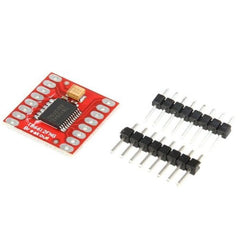
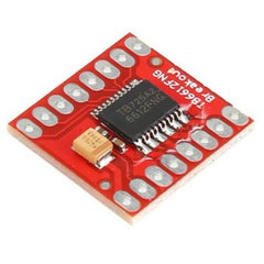
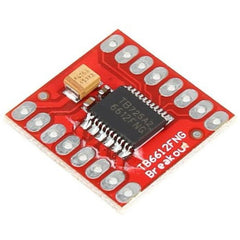
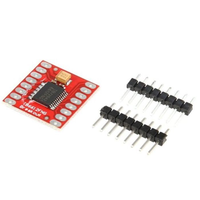
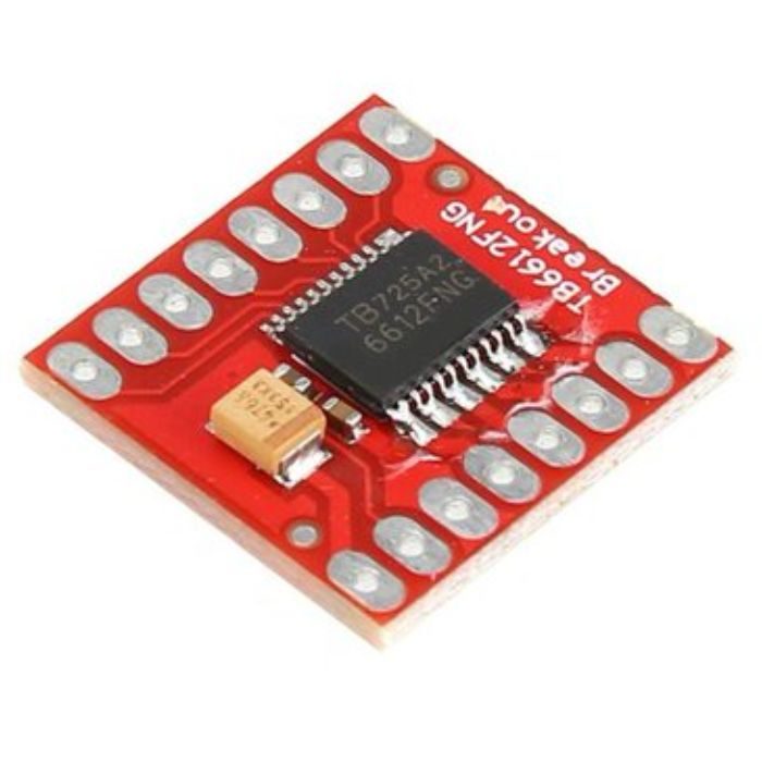
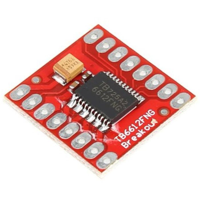
All components are installed on the board as shown. On both supply lines, decoupling capacitors are installed. The TB6612FNG has all of its pins broken out to two 0.1?? pitch headers, with input pins on one side and output pins on the other.
Understand the basics and see how this module compares to others in our guide: What Is a Motor Driver? L298N & L293D Explained
Features:
- Output current: Iout=1.2A(average) / 3.2A (peak)
- Standby control to save power
- CW/CCW/short break/stop motor control modes
- Built-in thermal shutdown circuit and a low voltage detecting circuit
- All pins of the TB6612FNG broken out to 0.1? spaced pins
- Filtering capacitors on both supply lines
Common Applications: Ideal for Line Follower Robots:
Thanks to its low voltage drop and efficient MOSFET motor driver design, the TB6612FNG is the preferred choice for space-constrained, battery-powered projects like line follower robots and micro-sumo bots. Unlike older drivers, it minimizes power loss as heat, ensuring your robot runs longer and more reliably on a single battery charge.
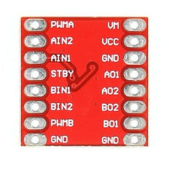
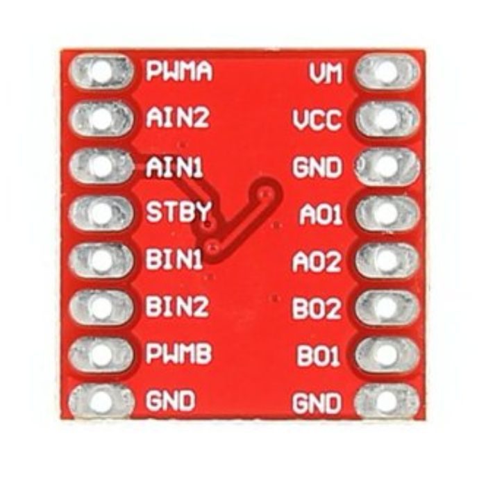
TB6612FNG Pinout (STBY, PWMA, AIN1/2):
- VM: Motor supply voltage (up to 15VDC)
- VCC: Logic supply voltage (2.7V to 5.5VDC)
- GND: Common ground
- STBY: Standby pin. Pull HIGH to enable the driver, LOW to enter low-power standby mode.
- AIN1 / AIN2: Direction control inputs for Motor A
- PWMA: PWM speed control input for Motor A (supports up to 100kHz)
- AO1 / AO2: Motor A output terminals
- (Repeat similarly for BIN1, BIN2, PWMB, BO1, BO2 for Motor B)
TB6612FNG vs L298N: Efficiency and Size:
While the L298N is a classic choice, the TB6612FNG motor driver is a significant upgrade for modern, space-constrained robotics. Here is a quick comparison:
| Feature |
TB6612FNG (Recommended) |
L298N |
| Output Technology |
MOSFET (Highly Efficient) |
BJT (Less Efficient) |
| Continuous Current |
1.2A per channel |
2A per channel |
| Peak Current |
3.2A (short pulse) |
3A (short pulse) |
| Voltage Drop & Efficiency |
Low voltage drop (Maximizes battery life) |
High voltage drop (~2V loss) |
| Heat Generation |
Minimal (No heatsink required) |
High (Requires bulky heatsink) |
| PWM Frequency |
Up to 100kHz (Silent & smooth) |
~1–20kHz (Can cause motor whine) |
| Size & Footprint |
Compact, breadboard-friendly |
Large, heavy, and bulky |
| Best Use Case |
Line follower robots, drones, battery-powered bots |
Heavy-duty, mains-powered, high-current robots |
Still not sure which one fits your project? Read our detailed comparison guide: DRV8833 vs L298N vs TB6612FNG: Which Motor Driver Should You Use?
Arduino Wiring Guide:
Connecting the dual DC motor driver to an Arduino is straightforward:
- Connect Arduino 5V to VCC and GND to GND on the module.
- Connect your battery’s positive terminal to VM and negative to GND.
- Connect Arduino Pin 10 to STBY (set HIGH in code to enable).
- Connect Arduino Pins 8 & 9 to AIN1 & AIN2 for direction.
- Connect Arduino Pin 6 (PWM) to PWMA for speed control.








 Chat


