2A Dual L298N Motor Driver Module with PWM Control
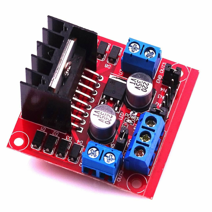
The L298N Motor Driver Module is a great choice for controlling motors! It contains a double H bridge L298N chip, which has a maximum voltage of 46V and a current of 2A. This L298N dual H bridge motor driver for Arduino works with a logic voltage of 5V and can drive motors with a voltage range of 5–35V, making it a reliable motor driver module for DC motor and robotics applications.
One cool feature of the L298N-based motor driver module is that it has current sensing for each motor, so you can easily check how they’re performing. It also features a heatsink to keep it cool while running, which increases efficiency. Also, there is a power-on LED indicator that indicates when it is active. The L298N Module is perfect for controlling DC and Stepper motors, switches, relays, robotic cars, arms, etc., making it the best motor driver module for Arduino projects for beginners and developers alike.
Note: The L298N uses BJT transistors, which inherently cause a ~2V voltage drop under load. For example, a 9V battery will deliver only ~7V to the motor. If you are building a battery-powered robot car and need maximum efficiency, we recommend upgrading to the TB6612FNG Motor Driver.
Perfect for controlling DC motors in your next 4WD or 2WD Arduino robot car kit.
Why Choose This Motor Driver Module?
- Reliable L298N dual H bridge motor driver for Arduino projects
- Ideal motor driver module for DC motor and robotics applications
- Beginner-friendly and widely supported
- High voltage and current handling capability
- Proven performance in robotics and automation
- Considered the best motor driver module for Arduino projects
Features:
- Uses an L298N IC for effective motor control.
- Includes a 78M05 Voltage Regulator for internal circuitry power.
- Jumper enables the voltage regulator for power supplies ? 12V; requires separate 5V for supplies > 12V.
- ENA and ENB pins control motor speed; IN1 & IN2 and IN3 & IN4 control motor direction.
- Features a Power LED for status monitoring.
- Compact design with integrated resistors and capacitors for stability.
- Easy to use with popular microcontrollers like Arduino.
Pinout
Wiring Diagram:

L298N Motor Driver Pinout: ENA, IN1–IN4, ENB
| Pin Name |
Description |
| IN1 & IN2 |
Motor A input pins. Used to control the spinning direction of Motor A. |
| IN3 & IN4 |
Motor B input pins. Used to control the spinning direction of Motor B. |
| ENA |
Enable pin for Motor A — allows PWM speed control of Motor A. |
| ENB |
Enable pin for Motor B — allows PWM speed control of Motor B. |
| OUT1 & OUT2 |
Output pins to Motor A — these connect to the two leads of Motor A. |
| OUT3 & OUT4 |
Output pins to Motor B — these connect to the two leads of Motor B. |
| 12V |
12V (or motor supply) input from DC power source — supplies power to the motors. |
| 5V |
Logic supply pin (5 V) — supplies power for the internal switching logic circuitry in the L298N IC. |
| GND |
Ground pin — common reference for the logic and motor power supply. |
L298N vs L293D vs TB6612FNG vs BTS7960: Which Motor Driver to Choose?
| Specification |
L298N |
L293D |
BTS7960 |
| Operating Voltage |
5V – 35V |
4.5V – 36V |
6V – 27V |
| Output Current (per channel) |
Up to 2A |
Up to 600mA |
Up to 43A |
| Number of Channels |
2 (Dual H-Bridge) |
2 (Dual H-Bridge) |
1 (Single H-Bridge) |
| PWM Control |
Yes (ENA/ENB Pins) |
Yes (Enable Pins) |
Yes (PWM Input Pins) |
| Logic Voltage |
5V |
5V |
3.3V – 5V compatible |
| Heat Dissipation |
Moderate (Built-in Heat Sink) |
Low (Needs external cooling for high load) |
High (Integrated powerful MOSFETs with heat sink) |
| Motor Type Supported |
DC Motors, Stepper Motors |
DC Motors, Small Steppers |
High-Power DC Motors |
| Efficiency |
Medium (BJT-based) |
Low (BJT-based) |
High (MOSFET-based) |
| Suitable For |
Robotics, Medium DC Motors |
Basic Projects, Low-Power Motors |
High-Torque Motors, Electric Vehicles |
Applications:
- Robotic Cars
- Robotic Arms
- Controlling the motor's speed and direction
5V Regulator Jumper: When to Remove It
The 5V regulator jumper on your L298N motor driver module controls whether the onboard voltage regulator is active. This regulator steps down your main motor battery voltage to 5V to power the module’s internal logic chips.
Knowing when to remove it is critical to prevent permanent damage to your board:
-
KEEP THE JUMPER ON: If your motor power supply is between 5V and 12V. The onboard regulator will safely power the logic circuitry.
-
REMOVE THE JUMPER: If your motor power supply is greater than 12V (up to 35V). Voltages above 12V will overheat and destroy the onboard 5V regulator.
Important: If you remove the jumper, the module’s logic will no longer receive power. You must supply a separate, stable 5V (e.g., from your Arduino’s 5V pin or a dedicated 5V BEC) directly to the 5V terminal on the motor driver. Without this external 5V logic power, the ENA, ENB, and IN1–IN4 pins will not respond to your Arduino robot car code.






 Chat


