How NRF24l01 Arduino Nano Works
Summary
The NRF24L01 is a widely used wireless communication module that enables low-cost and low-power data transfer between devices. In this blog, we will explore the operations of NRF24L01, its differences from NRF24L01+, SPI interface, versions of NRF24L01+, module pinout, coding, and transmitter and receiver connections. Whether you are an electronics hobbyist or a professional engineer, this informative guide will help you understand the working of NRF24L01 in detail.
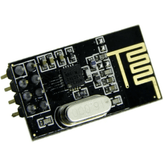
NRF24L01 is a single-chip transceiver module that uses the SPI protocol or an RF24 library. Here is all that you need to know about NRF24L01, how it works, NRF24L01 Arduino Guide, and NRF24L01 Module Pinout.
The transceiver module consists of fully integrated frequency synthesizers, a crystal oscillator, an amplifier, a demodulator, a modulator, and an Enhanced ShockBurst protocol engine.
Operations of NRF24L01
The operations which make NRF24L01 better than others are as given below:
Power Consumption
The module’s operating range is from 1.9 to 3.6V, and the logic pins are 5-volt tolerant, so it can easily be connected to an Arduino or any 5V logic microcontroller without using any logic level converter.
It supports programmable output power viz. 0 dBm, -6 dBm, -12 dBm, or -18 dBm and consumes around 12 mA during transmission at 0 dBm, which is even less than a single LED’s power consumption. The best factor is that it consumes 26 µA in standby mode and 900 nA in power-down mode. That makes it the go-to wireless device for low-power applications.
Other Specifications
Frequency range - 2.4 GHz ISM band
Maximum Air data range 2 Mbps
Modulation format - GFSK
Maximum Output power - 0 dBm
Operating Voltage - 1.9V to 3.6 V
Max. Operating Current - 13.5 mA
Minimum current (stand by) - 26µA
Logic Input - 5 V tolerant
Communication range - 800 m
read more : LED Interfacing with Arduino
Features of NRF24L01
The NRF24L01 has many features which make it more user-friendly. These features are as follows:
- Easy to pair: It is easy to pair with Microcontrollers Arduino Board ( MCU, ARM, PIC, AVR, SIM 32).
- Cost to performance ratio: It balances wireless transmission with performance and cost.
- Wide range: It can work up to a wide range of 100m with a standby current of 22 uA.
- Cost-effective: The wireless transceiver offers the aforementioned features, is more affordable than its competitors, and can be purchased for US $2!
Applications of NRF24L01
The application range of NRF24L01 is wide; it can be used from Wireless PCs to controllers and toys. Here is the list of some of its applications:
- Game controllers
- VoIP headsets
- 3-in-1 desktop bundles
- Wireless PC peripherals
- Sports watches and sensors
- Asset tracking systems
- Toys
- Mouse, keyboards, and remotes
- RF RFID
- Advanced media center remote controls
read more : Interfacing Proximity Sensors with Arduino
How is NRF24L01 different from NRF24L01+?
You must be amazed to see a “+” sign with some of the NRF24L01s in the market. You need not be confused anymore. Here is the difference between the two:
The NRF24L01+ is an updated version of the NRF24L01. It is capable of handling an extra 250kbps of on-air data rate while the NRF24L01 without “+” has only 1Mbps and 2Mbps.
Other than that, both can be considered identical to one another. Both versions can be mixed as long as 1 or 2 MBps are used as the data rate.
SPI interface of NRF24L01
The NRF24L01+ transceiver module communicates over a 4-pin Serial Peripheral Interface (SPI), and its maximum data range is 10Mbps. The SPI interface can configure the parameters such as frequency channel (125 selectable channels), output power (0 dBm, -6 dBm, -12 dBm, or -18 dBm), and data rate (250kbps, 1Mbps, or 2Mbps).
The SPI bus works on the concept of a master and a subordinate. Arduino is the master in most common applications, and the NRF24L01+ transceiver module is the subordinate. The number of subordinates on the SPI bus is limited; on the other hand, Arduino Uno can use a maximum of two SPI subordinates, i.e., two nRF24L01+ transceiver modules.
read more : Arduino Pin Configuration
Versions of NRF24L01+
The versions of NRF24L01+ are:
- NRF24L01+ wireless module is the first version of the NRF24L01+. It comes with an onboard antenna and is small and compact.
- NRF24L01+ 2.4 wireless module is the second version of the NRF24L01+.
- NRF24L01+ PA has an external IPX antenna and a power amplifier with a wide transmission range of 100m.
NRF24L01 Module Pinout
Here is the representation of the NRF24L01 Module pinout:

| Pin No. | Pin Name | Pin Specifications |
| 1 | VCC | This pin supplies power to the module. Its voltage can range from 1.9 to 3.9 volts. We can connect it directly to the 3.3V output of our Arduino. |
| 2 | CSN (Chip Select Not) | CSN is an active-LOW pin and is normally kept HIGH. It has to be kept high except when we are sending the device an SPI command or receiving data on the SPI bus from the microcontroller. |
| 3 | MOSI ((Master Out Slave In) | It is SPI input to the nRF24L01 that is used to receive data from the microcontroller |
| 4 | IRQ | It is an interrupt pin that alerts the master when new data is available to process. |
| 5 | MISO (Master In Slave Out) |
It is SPI output from the nRF24L01. It is used to send data to the microcontroller |
| 6 | SCK (Serial Clock) | It accepts clock pulses provided by the SPI bus master. |
| 7 | CE (Chip Enable) | It is the enable pin of the module. CE is used to select the mode of the NRF24L01 which is either transmit or receive, depending upon the mode it is currently in. |
| 8 | GND | GND is a Ground Pin. It is usually marked by enclosing the pin in a square to be used to identify the other pins. |
read more : How to use Buzzer with Arduino
Coding
The two codes for wireless communication are as follows:
Transmitters’ code:
/*
Transmitter coding for the nrf24L01 radio transceiver.
pins connections
VCC 3.3
GND GND
CE pin9
CSN pin8
SKL pin13
MOSI pin11
MISO pin12
*/

//Include Libraries
#include
#include
#include
//create an RF24 object
RF24 radio(9, 8); // CE, CSN
const byte address[6] = "00001"; //address through which two modules communicate.

void setup()
{
radio.begin();
//set the address
radio.openWritingPipe(address);
//set module as transmitter
radio.stopListening();
}
void loop()
{
//Send message to receiver
const char text[] = "Hello World";
radio.write(&text, sizeof(text));
delay(1000);
Receivers’ code:
/*
Transmitter coding for the nrf24L01 radio transceiver.
Pins connections
VCC 3.3
GND GND
CE pin9
CSN pin8
SKL pin13
MOSI pin11
MISO pin12
*/
//Include Libraries
#include
#include
#include

//create an RF24 object
RF24 radio(9, 8); // CE, CSN
//address through which two modules communicate.
const byte address[6] = "00001";

void setup()
{
while (!Serial);
Serial.begin(9600);
radio.begin();
//set the address
radio.openReadingPipe(0, address);
//Set module as receiver
radio.startListening();
}

void loop()
{
//Read the data if available in buffer
if (radio.available())
{
char text[32] = {0};
radio.read(&text, sizeof(text));
Serial.println(text);
}
}
Transmitter Connections:

Receiver Connections:

read more : Top 10 Robotic Projects for Beginners
Conclusion
In this blog post, we have learned that the NRF24L01 wireless module is a versatile and reliable solution for communication in embedded systems. Its various versions and SPI interface offer flexibility for different applications, while its pinout and coding are straightforward to implement. Whether you're building a transmitter or a receiver, the NRF24L01 module can easily be integrated into your project. And with its upgraded version, the NRF24L01+, you can take advantage of enhanced features for even better performance. So, don't hesitate to incorporate this powerful NRF24L01 module into your next project and take your operations to the next level!
If you appreciate our work don't forget to share this post and leave your opinion in the comment box.
Please do check out other blog posts about Popular Electronics
Make sure you check out our wide range of products and collections (we offer some exciting deals!)
Excerpt
Frequently Asked Questions
1. Can I use NRF24L01 without Arduino?
The chip called nRF24L01+ needs a microcontroller to work, but not necessarily an Arduino board. This chip cannot be programmed by the user, so a separate microcontroller is necessary to program and control it. Some people have used other microcontrollers like the 8-bit PIC or ATtiny85 successfully with the nRF24L01+.
2. What does nRF24L01 do?
The nRF24L01 is a wireless transceiver module that operates in the worldwide ISM frequency band commonly used for wireless communication. It uses GFSK modulation for data transmission and is designed for ultra-low power wireless applications. The module can send and receive data using an operating radio frequency.
3. Does nRF24L01 use WiFi?
The nRF24L01 module operates in the 2.4 GHz worldwide ISM frequency band and uses GFSK modulation for data transmission. It is an RF transceiver that allows wireless communication when connected to a microcontroller, including Arduino boards. However, it cannot establish a connection with a WiFi router or hotspot since its PHY layer differs from that of WiFi.
4. What is the NRF24L01 module used for with Arduino?
The NRF24L01 module is a popular wireless transceiver used with Arduino for creating low-power, long-range communication systems. It's ideal for remote control, sensor networking, and data transmission applications in robotics and IoT projects.
5. How do you connect NRF24L01 to Arduino Nano?
To connect the NRF24L01 to Arduino Nano, link the VCC to 3.3V, GND to ground, CE to digital pin 9, CSN to digital pin 10, SCK to pin 13, MOSI to pin 11, and MISO to pin 12. Ensure proper connections to avoid damage.
6. What library supports NRF24L01 on Arduino Nano?
The RF24 library supports the NRF24L01 module on Arduino Nano. This library simplifies the process of setting up and managing wireless communication, making it easier for developers to implement their projects.
7. What is the range of NRF24L01 wireless module?
The NRF24L01 wireless module typically has a range of about 100 meters indoors and up to 1,000 meters outdoors, depending on environmental factors and antenna configurations. Using external antennas can further extend this range.
8. How many bits or data rate does NRF24L01 support?
The NRF24L01 supports data rates of 250kbps, 1Mbps, and 2Mbps. It can transmit data in 1-byte to 32-byte packets, offering flexible configurations for various applications, allowing developers to choose rates that balance speed and reliability.
9. What is the difference between NRF24L01 and Bluetooth or WiFi modules?
The main difference is that NRF24L01 operates on a 2.4GHz frequency and is optimized for low-power, short-range communication with minimal data overhead. In contrast, Bluetooth and WiFi provide higher data rates but consume more power and are designed for different use cases.
10. How do you set up master and slave NRF24L01 communications?
To set up master and slave communications, initialize the NRF24L01 as a master in one Arduino and a slave in another. The master sends data requests while the slave listens for these requests. Use the RF24 library to handle these roles effectively.
11. What power and antenna considerations are needed for NRF24L01?
The NRF24L01 module requires a stable 3.3V power supply to function correctly. For antennas, ensure you use a PCB antenna or an external antenna according to your range needs, as this will significantly impact transmission distance and signal strength.
12. How to troubleshoot communication failures with NRF24L01?
To troubleshoot NRF24L01 communication failures, check power connections, ensure proper wiring, verify the library configuration, and test range limitations. Using a logic analyzer can also help diagnose transmission issues effectively.
13. What projects can you build using NRF24L01 and Arduino Nano?
With NRF24L01 and Arduino Nano, you can create various projects such as wireless sensor networks, remote-controlled vehicles, home automation systems, and data logging devices. Its versatility enhances the potential of your Arduino-based projects.


