How do I Power my Arduino?
Summary
Do you want to explore different ways to power your Arduino board? If the answer is Yes, Then check out this blog post which covers everything from using a USB cable, to batteries, power banks and it also discusses the advantages and disadvantages of each method and provide helpful tips and tricks to help you choose the best option for your project. Whether you're a beginner or an experienced maker, this guide will provide valuable insights into powering your Arduino board.
Hello! Welcome to this blog! In this article, we will be looking at how to power our Arduino. So stay tuned and let's get started!
Arduino provides various options in order to power it up. So let's take a look at them in detail.
Different ways to power Arduino?
Let's take a simple example to understand why we need to go through these different methods
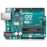
Example: Let's say we want to give a power supply to Arduino UNO which we will be using on our 2-wheeled robot. Since it is incompetent to power the Arduino from a laptop all the time, you will need to look at different options for powering the Arduino. In order to solve this problem, you need to understand the electrical ratings of the ports and pins so that you don't end up damaging Arduino which we did in this blog. Now we know the electrical ratings of ports and pins. Now we can make a battery pack based on these ratings and connect it to Arduino via a barrel jack or USB connector safely and run our robot.

read more : What is Arduino UNO
Now let us see different methods through which we can power supply Arduino:
1. USB B Port on Arduino
You can use USB A to USB B Arduino Cable to power the Arduino from your laptop. This will supply 5V to the board.
Note: ATmega328 MCU which is the main MCU in the Arduino board doesn't have USB support. In order to support USB, Arduino has another microcontroller ATmega16U2 which acts as a USB to serial converter and it interfaces between the USB port and atmega328 MCU. The reason for using an atmega16U2 instead of any other USB to serial converter is because of the low cost and since it's from the same microchip company.

2. Barrel jack plug
You can also use AC to DC barrel jack adapter to power your Arduino. You can give a power supply between 6V-20V to the barrel connector. The IC sitting next to the Barrel connector is a voltage regulator IC NCP 1117ST50 which can handle a max input voltage of 20V and converts it into a 5V regulated power supply.
Question: If we connect both the dc power jack and USB which will act power source to the MCU?
For this, we will need to go through the schematics of the Arduino board. For better understanding download the Arduino board schematic.

read more : Complete guide to Arduino Pro Mini
Note: This decision is taken with help of the OP-AMP LMV358ID comparator and FDN340P P-MOSFET which is placed close to OP-AMP in the schematic. P-MOS transistor to gets on when it’s connected to the ground.

Now looking at the OP-AMP circuit in the schematic we can see that Vin is the voltage from the barrel jack which gets halved through the voltage divider circuit and is then connected to the + terminal of OP-AMP. Now, this voltage at + terminal is compared to +3V3. If it's greater, the output of the opamp gets high it turns off the FDN340P MOSFET. Thus, disconnecting the USB power supply. The power supply via DC power jack is reduced to 5V from the NCP117ST voltage regulator and is then connected to the 5V net.
When Vin i.e. supply voltage from barrel jack is not given, + terminal is at 0V, and hence the output of the op-amp is low which turns on the FDN340P MOSFET and connects the USB power supply to the 5V net. This is how the power supply decision is taken when both barrel jack and USB are plugged.
read more : Smart Dustbin using Arduino
3. Vin Pin
As shown in the figure, you can give the power supply to the Vin pin directly too instead of giving it from the barrel jack ( which we saw earlier). So the working is same as the previous. You can give a maximum of up to 20V. But, 12V is the recommended voltage. This 20V is then converted to 5V and supplied throughout the board.
read more : Interfacing Proximity Sensors with Arduino
4. 5V Pin

There is one more method through which we can give power supply and that is by giving a 5V power supply directly to the 5V pin.

But, from the figure, we can see that it is bypassing the NCP117 voltage regulator i.e. this 5V power supply which we are giving is directly getting connected to the 5V net. Since we are directly connecting it to the 5V net we need to make sure that we give a stable and regulated power supply to this pin.
read more : Obstacle Avoider Robot Using Arduino and IR Sensor
Conclusion
In this blog, we have seen different methods through which we can give power supply to the Arduino, and also we have seen how the power supply is manipulated internally.
If you appreciate our work don't forget to share this post and leave your opinion in the comment box.
Please do check out other blog posts about Interfacing ACS712 with Arduino , Arduino Interfacing with Ultrasonic Sensor , LED Interfacing with Arduino , Interfacing GSM Module with Arduino , Interfacing MAX30100 Pulse Oximeter with Arduino , IR Sensor Interfacing with Arduino , How to connect ZMPT101B to Arduino and How to use Buzzer with Arduino.
Make sure you check out our wide range of products and collections (we offer some exciting deals!)


