


Summary
In this captivating blog post, we delve into the world of fire detection and notification systems powered by Arduino. Starting with an insightful introduction, we explore the pivotal role played by this technology in ensuring safety. We then deep-dive into the heart of the system – the Flame Sensor and the GSM SIM800C Modem Shield with Antenna. Discover the essential components, the ingenious working principle, and a detailed circuit diagram breakdown. Unveil the magic of the code that makes it all tick, witness the system's impressive output, and finally, wrap it up with a compelling conclusion that underscores its significance in modern safety measures. Don't miss this enlightening journey through innovation and safety!
Introduction
Introducing Fire Detection and Notification Alarm using Arduino: This innovative solution is designed to alert you in case of fire. It uses an advanced combination of sensors, detection circuits, and notification systems powered by Arduino technology. With this alarm system working 24/7, users can rest assured knowing they have a reliable way to detect any potential fires or smoke emissions even when away from home. Utilizing intuitive software that works with the latest tech trends – like Bluetooth integration for remote monitoring – this state-of-the-art Arduino-based technology makes sure all homeowners are safe at all times!

read more : Exploring LCD Displays and Arduino UNO
Components and Supplies


Arduino Uno R3 Original
- Rs 2,619/-
- Rs 2,619/-
-
Rs 2,649/-


Heat Flame Sensor
- Rs 33/-
- Rs 33/-
-
Rs 53/-


SIM 800C GSM Modem with SMA Antenna
- Rs 746/-
- Rs 746/-
-
Rs 850/-


9V Original HW High-Quality Battery
- Rs 25/-
- Rs 25/-
-
Rs 35/-


Piezo Buzzer (Big) 6-12V
- Rs 30/-
- Rs 30/-
-
Rs 44/-


GL12 840 Points Solderless Breadboard
- Rs 70/-
- Rs 70/-
-
Rs 90/-


5mm Round Red Diffused Led (Pack of 10)
- Rs 13/-
- Rs 13/-
-
Rs 14/-


5mm Green Led (Pack of 10)
- Rs 15/-
- Rs 15/-
-
Rs 19/-


Jumper Wire Set - M2M, M2F, F2F (40 pcs each)
- Rs 139/-
- Rs 139/-
-
Rs 169/-


9V Battery Snap Connector (Pack of 5)
- Rs 38/-
- Rs 38/-
-
Rs 49/-
Flame Sensor
A flame detector is a sensor designed to spot and respond to flames or fires. When it detects a flame, it can trigger actions like sounding an alarm, shutting off a fuel line (e.g., propane or natural gas), or activating a fire suppression system. The project employs an IR Flame sensor, also known as a Fire sensor module or flame detector sensor.
Various methods exist for flame detection, including Ultraviolet detectors, near IR array detectors, infrared (IR) detectors, Infrared thermal cameras, and UV/IR detectors.
When a fire burns, it emits a small amount of infrared light. This light is captured by the photodiode (IR receiver) on the sensor module. An Op-Amp checks for voltage changes across the IR Receiver. If a fire is detected, the output pin (DO) goes to 0V (LOW); otherwise, it stays at 5V (HIGH).

read more : IR Sensor Interfacing with Arduino
The project uses an IR-based flame sensor, a high-speed and highly sensitive NPN silicon phototransistor. It detects infrared light in the 700nm to 1000nm wavelength range and has a detection angle of about 60°. The flame sensor module contains a photodiode (IR receiver), resistor, capacitor, potentiometer, and LM393 comparator integrated circuit. Sensitivity can be adjusted via the onboard potentiometer. The sensor operates on 3.3V to 5V DC, providing a digital output. A logic high on the output signals the presence of a flame or fire, while a logic low indicates the absence of a flame or fire.
Pin description
|
Pin |
Description |
|
Vcc |
3.3 – 5V power supply |
|
GND |
Ground |
|
Dout |
Digital output |
read more : Arduino Interfacing with Ultrasonic Sensor
GSM SIM800C Modem Shield with Antenna:
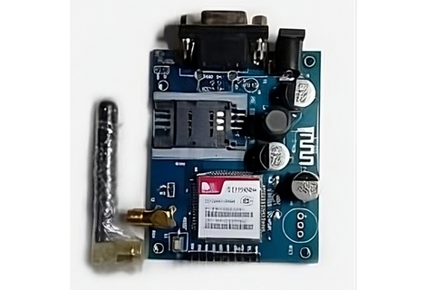
This one small modem can help use the GSM network of a SIM card. It can be used to make text messages and calls. It can also provide the user with the GPS location. Its low form factor and comparatively lower power requirements make it a good option for this project.
read more : Interfacing Proximity Sensors with Arduino
Components Required
- Flame Sensor Module
- GSM SIM800C Modem Shield with Antenna
- 5mm Red LED
- 5mm Green LED
- Passive Buzzer
- Arduino UNO
- Breadboard
- Jumper Cables
- 9V Battery
- Battery 9V Snap Connector + DC Jack
Read Buzzer Arduino tutorial for beginners.
Working Principle:
- The Flame Sensor which consists of a phototransistor will conduct some amount of current when infrared rays from a Fire source is incident on the sensor.
- This, in turn, will cause the sensor to output a digital high signal.
- Our Arduino will be continuously listening to the output of the module and as soon as detect its status as high,
- We will send a request to the GSM SIM800C to send a text message and a call to the predefined number.
- And Bam! You just received the Alert.
The circuit diagram and explanation:

- First Connect the Cathode (+ve) of the 5mm Red LED to digital pin 9 (D9) on Arduino.
- Similarly, connect the Cathode (+ve) of the 5mm Green LED to digital pin 8 (D8) on Arduino.
- Now, connect the Anode (-ve) of both the LED’s to the Ground pin on Arduino.
- Then connect the +ve of Buzzer to digital pin 5 (D5) on Arduino.
- Next, connect the D0 pin on the Flame Sensor Module to digital pin 5 (D5) on Arduino.
- Connect the VCC and GND on the Flame Sensor Module to the 5V pin and the Ground pin on Arduino respectively.
- Now, connect the TX and RX of SIM800C to the RX (D0) and TX (D1) of Arduino respectively.
- Finally, give the SIM800C power supply using a 9V battery or a 12V Power Supply. Also, ensure that all systems are having common ground by connecting the ground on SIM800C to Ground Pin on Arduino.
- This completes our connection.
read more : How NRF24l01 Arduino Nano Works
Code:
/*
* Flame detection and notification system
* Code developed by Jatin Vira
*/
#define redled 9 //This will define "redled" as number 9 whenever it occurs again in code
#define greenled 8 //This will define "greenled" as number 8 whenever it occurs again in code
#define BuzzerPin 7 //This will define "BuzzerPin" as number 7 whenever it occurs again in code
#define FlamePin 5 //This will define "FlamePin" as number 5 whenever it occurs again in code
boolean Flame_Sensor_Value = HIGH; //This variable will store the value of Flame Sensor
void setup() //This will run only once and at the start of the program
{
/*By using pinMode function we will declare state
* of each pin as Output/Input depending on their nature
* We use OUTPUT when we have to define the output state of the pin (0/5V)
* We use Input when we have to read
*/
pinMode(BuzzerPin, OUTPUT);
pinMode(redled, OUTPUT);
pinMode(greenled, OUTPUT);
pinMode(FlamePin, INPUT);
Serial.begin(9600); //Set the baud rate to 9600 bit per second
}
void loop() //This will run indefinitely till the program is terminated
{
Flame_Sensor_Value = digitalRead(FlamePin); //Store the value of sensor in this variable
if (Flame_Sensor_Value == LOW) //check if condition matches with fire detection state
{
/*Turn on Indicators*/
digitalWrite(BuzzerPin, HIGH); // Turn Buzzer on
digitalWrite(redled, HIGH); // Turn Red LED on
digitalWrite(greenled, LOW); // Turn Green LED off
/*Responsible for sending SMS*/
Serial.println("AT+CMGF=1"); //Selects SMS message format as TEXT
delay(1000); // Delay of 1 second
Serial.println("AT+CMGS=\"+91xxxxxxxxxx\""); // Replace x with mobile number
Serial.println("FIRE IN THE HOUSE"); // The SMS text you want to send
Serial.println((char)26);
delay(500);
/*Responsible for making a CALL*/
Serial.println("ATD+ +91xxxxxxxxxx;"); // Replace x with your mobile number
delay(5000); //Wait for Call to reach
Serial.println("ATH"); //Hang up the Call
}
else
{
digitalWrite(BuzzerPin, LOW); // Turn Buzzer off
digitalWrite(greenled, HIGH); // Turn Green LED on
digitalWrite(redled, LOW); // Turn Red LED off
}
}
Output

- As soon as the sensor detects that some form of IR radiation is incident, it outputs a low signal which when read by the microcontroller outputs a serial print command which has AT commands responsible for making a call and sending a text message to a predetermined number.
- A call and a text SMS are received along with the Red LED glowing and the buzzer ringing.
read more : Top 10 Arduino Projects for Beginners
Conclusion:
Our exploration of Fire Detection and Notification Alarm using Arduino has shed light on a crucial aspect of safety in today's world. The integration of a Flame Sensor, GSM SIM800C Modem Shield with Antenna, and other essential components has allowed us to create a robust fire detection system. Understanding the working principle, dissecting the circuit diagram, and implementing the code have empowered us to craft a reliable alarm system. With this setup, real-time notifications in case of a fire emergency are just a text message away. As we wrap up our journey through this project, remember that innovation and technology play pivotal roles in safeguarding lives and property. Stay safe, stay vigilant!
If you appreciate our work don't forget to share this post and leave your opinion in the comment box.
Please do check out other blog posts about Popular electronics
Make sure you check out our wide range of products and collections (we offer some exciting deals!)