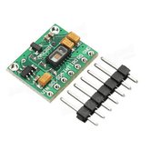
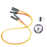
Interfacing Pulse Sensor with Arduino (Heart Rate Monitor)
The sensor is quite simple and it takes little effort to set it up. All you need to do is to gently place your fingertip onto the sensor for a few seconds for the Arduino’s Serial Monitor to display the heart rate.
How Does the Pulse Sensor Work?
The sensor has two surfaces. On one side, we have the Light Emitting Diode (LED) and an Ambient Light Sensor, while on the other side we have the circuitry for the diode and light sensor along with the circuitry for the noise cancellation and amplification photo-plethysmography. It detects the change in volume of blood in the veins, at the given instance based on how much light is reflected back from the LED and falls on the light sensor. The amount of blood in the given instance depends on the heart rate and hence, we can derive the BPM via a simple calculation based on the intensity changes detected by the sensor.
Wiring Diagram
The wiring of the sensor is quite simple and straightforward. It contains three terminals, VCC, GND and Signal Output (analog out). It needs to be connected to Arduino’s corresponding 5V (VCC), GND and A0 (Analog In 0)
The terminals of the sensor are indicated on the circuitry side of the sensor (shown in red). For easier inference, you can also follow the colour of the wiring to the respective terminals on the both sides.
Code
The code required to operate the sensor can be obtained through an Arduino Library Manager and is called Pulse Sensor Playground.
To download Pulse Sensor Playground;
- Open Arduino Program
- Open Sketch from the menu bar and click on Include Library, and then Manage Libraries
- Search for Pulse Sensor Playground
- Select the result and click on install
- Close the Library Manger
In order to use the Example code used in this tutorial;
- Click on File from the menu bar
- Click on Examples, then scroll down to find Pulse Sensor Playground
- Open Getting_BPM_to_Monitor
The basic functionality of the selected code and the library above is to find out the changes in light intensity every few milliseconds and then to calculate the BPM from the frequency of the changes recorded.
Now, compile and upload the sketch and voila, you have a DIY heart rate monitor ready.
Gently place your finger onto the part of the sensor with the heart symbol and you should be able to see your heart rate displayed in Arduino’s Serial Monitor (Tools -> Serial Monitor). Ensure you give it a few seconds for the readings to stabilize
Applications
A simple heart-rate sensor can open a wide variety of potential projects that can be used in potential real world application (Note: This particular sensor should only be used for prototyping purposes and only a professional FDA approved sensor should be used for any sort of real world deployment)
Some of the projects, that can come forth from this include;
- Sleep tracking
- Activity Monitor
- Anxiety Monitoring
- Remote Patient Monitoring and Alarm System
- Wearable devices, etc
This is an open source hardware and you can easily incorporate live heart rate into any projects. So get creative!
In the upcoming tutorial, we will be showing you how to interface the Pulse Sensor with Raspberry Pi and stream the data over the internet for remote monitoring of the heart rate.
Disclaimer: This is not an FDA approved sensor and hence it should not be used for medical applications or used in place of a certified heart rate sensor/device. The actual readings from the sensor may not be accurate and a certain amount of noise in the data is to be expected.


