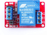
What is Relay? - Working, Applications & Types
Summary
Have you ever wondered what a relay switch is, and why it's used in technology? It can play an essential role in controlling circuits within many different types of applications.
In this blog post, we'll explain what it is and its working principle – as well as its various types – so that you have all the details needed to determine whether it fits your specific needs.
Introduction
Relays are an important part of the electrical system. They serve as switches that transfer signals to other devices, allowing for remote control or automated operations in a wide range of applications.
Electronic engineers have been using this technology comfortably over decades now with ever growing advancement towards more environment friendly solutions including wireless ones! Now let's learn about what a relay is in electrical.
What is Relay?
A relay is an electromagnetic switch or device that can be used to control electrical circuits. It works by opening and closing power supply lines in order to optimize the flow of current within a circuit.
Along with controlling applications, it has other benefits such as providing protection from overcurrents due to short circuits, helping direct energy more efficiently throughout systems, and allowing for remote operation through automation processes.

For example, at a busy airport, these switch modules control conveyor belts and ensure luggage moves efficiently. When a cart triggers a sensor, it sends a signal to a relay, which activates the belt's motor.
This sequence repeats, Similar to relay racers passing batons, it smoothly transfers luggage from one point to another.
Working Principle of Relay Module?
A relay is an electrical device that helps to complete the circuit and thus controls a large amount of electricity with low power.
It operates on simple electromagnetic induction principles:
When an electric current passes through a wire winding within the relay’s coil, it creates magnetic flux which pulls down its armature and closes contacts connected mechanically to a second set of terminals functioning as output switches from one location to another.
This process continues until either power is cut off (opening circuits) or when the manual button is pressed internally, which reverts back to resetting operation (closing circuits).
An electromechanical switch that opens and closes circuits is called a relay. The main function of this device is to establish or break contact by a signal, and it does not need human interaction to be turned on or off.
It is mostly utilised to employ a low-power signal to operate a high-powered circuit. Typically, a DC signal is utilised to operate a circuit that is powered by high voltage, such as when using microcontrollers to operate AC home appliances.
Construction:

- It is physically and electrically driven. It consists of electromagnetic fields and contact sets that carry out the switching function. Relay construction is primarily divided into four groups. They are the housing, terminations, electromechanical design, bearings, contacts, and terminations.
- The most crucial essential component of the switch module that influences dependability is the contacts. Good contacts have minimal contact resistance and little wear. The type of current to be interrupted, its size, frequency, and voltage of operation are only a few of the variables that affect the contact material choice.
- The magnetic circuit design and the mechanical attachment of the armature, yoke, and core are both included in the electromechanical design. The resistance of the magnetic route is minimized to increase the circuit's efficiency. Soft iron electromagnets typically have coil current and voltage limitations of 5 amps and 220 volts, respectively.
Relay Contact Types
It can be classified, depending on the poles and throws
- Single Pole Single Throw (SPST)
- Single Pole Double Throw (SPDT)
- Double Pole Single Throw (DPST)
- Double Pole Double Throw (DPDT)
Single Pole Single Throw (SPST):

Fig. 2. Circuit diagram of SPST
A switch with only one input and one output is referred to as a Single Pole Single Throw (SPST) switch.
The single input terminal and single output terminal are shown here. An SPST switch serves as an on/off switch in a circuit.
The circuit is activated when the switch is closed. The circuit is cut off when the switch is in the open position.
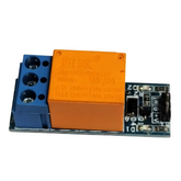
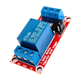
Check out 5V Relay Module
Single Pole Double Throw (SPDT):

Fig. 3. Circuit diagram of SPDT
An SPDT switch allows for the connection of two outputs to a single input.
This indicates that it has two output terminals and one input terminal. A single pole double throw switch has several applications in a circuit. Whether or not the circuit may be utilized as an on/off switch depends on how it is connected.
Or it can connect circuits to any two different paths that a circuit may need to follow in order to function. For instance, a printer's Ready Mode and Standby Mode can be created by connecting an SPDT switch.
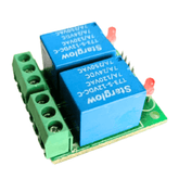
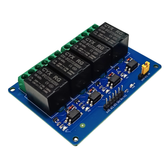
Check out 12V Relay Module
Double Pole Single Throw (DPST)

Fig. 4. Circuit diagram of DPST
A double pole single throw (DPST) switch is used to link two source terminals to the corresponding output terminals.
It contains four terminals (but never to each other). In an "ON/OFF" configuration, a DPST switch can be utilised with its terminal pairs either connected ("ON") or disconnected ("OFF").
Double Pole Double Throw (DPDT):

Fig. 5. Circuit diagram of DPDT
A Double Pole Double Throw (DPDT) switch is a switch with two inputs and four outputs, each of which can be connected to one of the two corresponding outputs. A double pole, the double switch has two possible orientations for each of its terminals. Due to its versatility, the double pole, double throw switch. It may be connected to 4 distinct outputs with just 2 inputs. A circuit can be rerouted into one of two operating modes.
Check out Solid State Relays
Types of relays:
Relays are an essential equipment for countless applications in the power system. They come in a variety of types and can be used to perform various functions related to protection, safety, control or automation.
Depending on what they’re being used for, these may take different form factors such as electromechanical relays (EMR), static transfer switch (STS) or solid-state relay (SSR).
EMRs use current flow via coils to create magnetic fields, which, under certain circumstances, activate contact mechanisms to open or close circuits.
When transferring loads between two sources, STS is typically used to provide a continuous supply with little interruption.
Instead of utilizing moving elements, SSRs rely on semiconductor devices like transistors and transducers, which makes them more costly than other types but more dependable.
Relays can be divided into several types based on their features, architectural uses, etc. Here, we've included a few of the more common types.
- Electromagnetic
- Latching
- Electronic
- Non-Latching
- Reed
- High-Voltage
- Small Signal
- Time Delay
- Multi-Dimensional
- Thermal
- Differential
- Distance
- Automotive
- Frequency
- Polarized
- Rotary
- Sequence
- Moving Coil
- Buchholz
- Safety
- Supervision
- Ground Fault
How to Test Relays?

Before testing a relay, you need to prepare it. Just follow these steps below to prepare your electromechanical switch;
Steps for Preparing your Relay:
Step 1: Check for damage indicators like melting or blackening. Verify that the LED indications are off if the relay is not in use.
Step 2: Take great care while handling capacitors and carefully unplug all power sources, including line voltage and batteries.
Step 3: To ensure precise testing and prevent mistakes, refer to the relay schematic or datasheet for pin layouts and specifications.
Steps for Testing a Coil Relay:
Step 1: First, identify the relay's component number. This number is frequently spotted on the electromechanical switch casing. Once you have this information, check the datasheet to establish the control coil's voltage and current requirements.
The purpose of this critical step is to ensure that the module receives the proper amount of electricity.
Step 2: Some relays have diode protection to prevent the logic circuitry from harm caused by increased noise levels. A triangle with a bar across one corner is commonly used to represent diode protection.
Check to ensure that the diode's orientation matches the positive connection on the control coil.
Step 3: Look at the contact structure, taking note of how many poles it has and whether or not it has normally closed (NC) and normally open (NO) connections.
You may find this information on the electromechanical switch casing or in the datasheet. The connections between each pole will be shown in schematic drawings.
Step 4: Make sure the contacts are disconnected before turning on the relay. Determine the resistance between each pole and the corresponding NC and NO contacts using a digital multimeter (DMM).
In this scenario, resistance on the NO connection should be infinite, whereas resistance on the NC connection should be zero ohms.
Step 5: After verifying the status of the disconnected connections, activate the relay coil using power from a suitable source. Verify that the voltage level meets the requirements listed in the datasheet.
Remember the polarity of the independent power supply if your relay has diode protection. There should be a noticeable clicking sound when the switch module is correctly powered.
Step 6: Once it is operating, test the resistance between each pole and its corresponding NC and NO contacts again using the Digital Multimeter. The electrified state need to exhibit a value reversal in comparison to the de-energized state.
More precisely, NC connections should have infinite resistance while NO connections should have 0 ohms of resistance.
Steps for Testing Solid-State Relays:
Step 1: To evaluate the integrity of the relay, use an ohmmeter. Make sure the power to the control is off. Put the ohmmeter across the terminals that are usually open (N.O.).
The relay should show an open circuit (OL) when it is disconnected. When control power is applied, a working switch module will display a closed circuit, usually at 0.2Ω.
Step 2: Change the multimeter's mode to diode test. Cross the A1(+) and A2(-) terminals using probes.
For silicon transistors, a measurement of around 0.7V or 0.5V for germanium transistors indicates typical operation. Any variation points to a malfunctioning relay.
Step 3: It is best to keep solid-state relays cool to maximize their lifespan and functionality. Consider DIN rail packages or block mountings for efficient heat dissipation.
It is important to employ caution when using SCR relays in heating applications since they may fail due to temperature fluctuations.
Applications of Relay:
When galvanic isolation is desired, relays are employed whenever it is necessary to control a high-power or high-voltage circuit with a low-power circuit.
Relays were first used on long telegraph lines, where a contact may be controlled by a weak signal received at an intermediate station, renewing the signal for further transmission.
Small, low-voltage wire and pilot switches can be used to control high-voltage or high-current equipment. The following are the 8 major applications:
- Lighting control systems
- Industrial process controllers
- Traffic control
- Motor drives control
- Protection systems of the electrical power system
- Computer interfaces
- Automotive
- Home appliances
Conclusion:
In this blog, we understand what is a relay, working, contact types and different types of relays and applications. We have seen It works on the principle of electromagnetic attraction when it gets energized it operates according to the signal given.
Nowadays, this signal is given by the micro-controllers or microprocessors. These are also used in power system operations to detect and prevent the fault.
If you appreciate our work don't forget to share this post and leave your opinion in the comment box.
Please do check out other blog posts about Popular Electronics
Make sure you check out our wide range of products and collections (we offer some exciting deals!)
Excerpt
Frequently Asked Questions
1. What is Difference Between Relay and Switch?
A relay is an electrically operated switch that harnesses the power of an electromagnet to either open or close a circuit, while a switch is a mechanical device that opens or closes a circuit physically. Switches can be activated manually, but relays are typically controlled by electrical signals. When it comes to usage, switches are utilized in applications that require low power, whereas relays are employed in high power applications where manual activation is neither feasible nor practical.
2. What are the four functions of a Relay?
It can be defined as DC and AC both types. DC relays use a DC power supply and a small coil wire with several turns due to the wire's high coil resistance. whereas, the coil windings on AC relays are particularly built for AC characteristics. Both types operate electrical circuits by opening or closing contacts in response to input signals.
3. Are Relays AC or DC?
A 4-pin relay has two pins (30 & 87) that control one circuit and two other pins (85 & 86) that control the coil. With four pins it can be classified as Normally Closed (NC) or Normally Open (NO). When a coil is engaged, a normally closed relay shuts off the circuit's electricity, whereas a normally open relay turns it on.
4. What is the work of 4 pin Relay?
Relay does not have its own circuits. Instead, it controls them.
5. How many circuits are in a relay?
One component is known as the control circuit, and it functions similarly to a small-power route. It features a coil and wire connectors. When you add electricity to a coil, it produces a magnetic field. The other component is the load circuit, which is comparable to the high-power path.
6. What is pole in relay?
It works as a switch in this circuit. When it is engaged by the control circuit, electricity flows through the load circuit. When switched off, it stops the flow of power. So, even though these switch modules does not have its own circuits, it is still highly valuable for regulating energy in various parts of the device.
7. What is a relay and how does it work?
A relay is an electromechanical switch that allows one circuit to control another. It consists of a coil, an armature, and one or more sets of contacts. When current flows through the coil, it creates a magnetic field that moves the armature, closing or opening the contacts. This enables control over high-voltage circuits using a low-voltage signal.
8. What are the main types of relays used in electronics?
The main types of relays used in electronics include electromagnetic relays, solid-state relays, reed relays, and thermal relays. Each type has unique characteristics suited for specific applications, such as switching speed, load capacity, and durability. Understanding these types helps in selecting the right relay for your project.
9. How does an electromagnetic relay function?
An electromagnetic relay functions by using a coil that generates a magnetic field when energized. This field attracts an armature that either opens or closes the relay contacts. The process can control a larger current circuit using a smaller input signal, making it ideal for automation and circuit protection.
10. What is the difference between AC and DC relays?
The main difference between AC and DC relays lies in their power supply type. AC relays are designed for alternating current, providing better coil performance under varying voltage. DC relays work with direct current and can be more sensitive, with quick response times. Always check your application needs before choosing a relay.
11. What is a solid-state relay?
A solid-state relay (SSR) uses semiconductor devices instead of mechanical parts to switch circuits. It offers advantages like faster switching, longer lifespan, and no moving parts, making it ideal for high-cycle applications. SSRs are also quieter and less prone to failure than traditional relays, enhancing reliability in your projects.
12. Where are relays used in daily life?
Relays are commonly found in various everyday applications, such as home appliances, automotive systems, and automation controls. They enable functions like turning lights on and off, managing heating systems, and controlling motors. Understanding their applications can help you appreciate their role in modern electronics.
13. What causes a relay to fail or malfunction?
Relay failures can result from several factors, including electrical overload, corrosion of contacts, mechanical wear, or overheating. Environmental conditions like humidity and dust can also affect performance. Regular maintenance and proper specification help in preventing relay malfunctions for reliable operation.
14. Can a relay be used for high-voltage circuits?
Yes, relays are designed for use in high-voltage circuits. They can safely switch high-voltage loads while protecting low-voltage control signals. Always choose a relay with the appropriate voltage and current ratings to ensure safe and efficient operation in your application.
15. What is the working principle of a 5V relay module?
A 5V relay module operates using an electromagnetic coil powered by a 5V signal. When the signal is applied, the coil energizes, creating a magnetic field that moves an armature to open or close contacts. This allows control of higher voltage devices while requiring only a low-power control signal.
16. How does a relay improve circuit safety and automation?
Relays enhance circuit safety by isolating low-voltage control circuits from high-voltage loads, minimizing risks. They also automate processes by enabling remote control and timing functions. By using relays, you can create smarter systems that respond automatically to changes, improving overall efficiency in your electronic projects.


