Building a Simple ESP32 LED Web Server
Summary
In the world of IoT (Internet of Things), the ESP32 microcontroller has become a popular choice for developers and hobbyists alike due to its powerful features and built-in Wi-Fi and Bluetooth capabilities. One of the most exciting applications of the ESP32 is creating web servers that allow you to control devices remotely over the internet. In this tutorial, we will guide you through the process of building a simple LED web server using the ESP32. By the end of this project, you'll be able to control an LED connected to the ESP32 from any device with a web browser, whether it's your smartphone, tablet, or computer.
Whether you're a beginner or an experienced developer, this project is a great way to dive into the world of IoT and explore the potential of the ESP32. Let's get started!
Episode EE01:

Do you know What is Esp32 Development Board? read now!
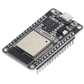
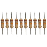
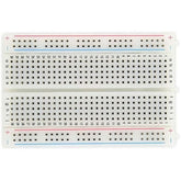
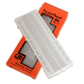
Hardware Required:
Circuit Diagram ESP32 LED Web Server:

| Component | ESP32 Pin | Description |
|---|---|---|
| LED (Anode) | GPIO Pin (e.g., GPIO 2) | Connect the positive (longer) leg of the LED to a GPIO pin of the ESP32 (e.g., GPIO 2). |
| LED (Cathode) | GND | Connect the negative (shorter) leg of the LED to the Ground (GND) pin of the ESP32. |
| Resistor (e.g., 220Ω) | Between LED Anode and GPIO Pin | Add a resistor in series with the LED to limit the current and prevent damage to the LED and ESP32. |
Check out our latest blog Build Your Security Camera Using ESP32-CAM - A Step-by-Step Guide
Programming
Before uploading the code. In this area, make sure to update the network credentials to your SSID and password.
const char* ssid = " REPLACE_WITH_YOUR_SSID";
const char* password = " REPLACE_WITH_YOUR_PASSWORD";
Complete Code
ESP32 Web Server
"); // Display current state, and ON/OFF buttons for GPIO 12 client.println("
GPIO 12 - State " + output12State + "
"); // If the output12State is off, it displays the ON button if (output12State=="off") { client.println("
ON
"); } else { client.println("
OFF
"); } // Display current state, and ON/OFF buttons for GPIO 14 client.println("
GPIO 14 - State " + output14State + "
"); // If the output14State is off, it displays the ON button if (output14State=="off") { client.println("
ON
"); } else { client.println("
OFF
"); } client.println(""); // The HTTP response ends with another blank line client.println(); // Break out of the while loop break; } else { // if you got a newline, then clear currentLine currentLine = ""; } } else if (c != '\r') { // if you got anything else but a carriage return character, currentLine += c; // add it to the end of the currentLine } } } // Clear the header variable header = ""; // Close the connection client.stop(); Serial.println("Client disconnected."); Serial.println(""); } }
Upload the code to the esp32 board
Finding the IP address of the ESP32 board
1. Open the Serial Monitor in the Arduino IDE

2. Select a baud rate of 115200

3.Wait for the ESP32 board to connect to the WiFi network
4.Once the ESP32 board is connected to the WiFi network, it will obtain an IP address from the network. The Serial Monitor will display the IP address of the ESP32 board.

Result:

Hey want to hunt treasures with ESP32 then check this blog - TREASURE HUNT USING ESP32 (BLE SCANNER)
The Working Concept of the Project
- ESP32 as a Web Server: The ESP32 is programmed to function as a web server, meaning it can host a simple web page accessible from any device connected to the same network. When a user opens this web page in a browser, they can control the LED by sending commands to the ESP32.
- Wi-Fi Connection: The ESP32 connects to your Wi-Fi network, allowing it to communicate with other devices, such as your smartphone or computer. Once connected, the ESP32 is assigned an IP address, which you will use to access the web server.
- User Interface: The ESP32 serves a simple HTML page that contains buttons or switches for controlling the LED. For example, the page might have buttons labeled "Turn ON" and "Turn OFF." These buttons send HTTP requests to the ESP32 when clicked.
- Processing Requests: When you press a button on the web page, an HTTP request is sent to the ESP32. The ESP32 interprets this request and determines whether it needs to turn the LED on or off. It then sends the appropriate signal to the GPIO pin controlling the LED.
- LED Control: The ESP32 controls the LED by toggling the voltage on a specific GPIO pin. If the user presses the "Turn ON" button, the ESP32 sets the pin to HIGH, and the LED lights up. If the "Turn OFF" button is pressed, the pin is set to LOW, and the LED turns off.
- Real-Time Feedback: The changes in the LED state occur in real-time, allowing the user to see the result of their actions immediately. The web interface updates accordingly to reflect the current status of the LED.
Also read LED Interfacing with Arduino.
Conclusion:
Please do check out other blog posts about Popular electronics
Check out other related blog posts about Drones: Drone transmitter and receiver , Drone motors and Getting started with a Quadcopter
Make sure you check out our wide range of products and collections (we offer some exciting deals!)


