ARDUINO BASED WATER LEVEL MONITORING
Summary
Dive into the world of Arduino-based water level monitoring with our latest blog! Learn about the crucial Ultrasonic Sensor, essential components, and a detailed circuit diagram. Explore the ins and outs of Arduino programming, calibration, and testing. Uncover quick fixes for common issues and master the art of data visualization. Discover exciting real-world applications and wrap up with key takeaways. Don't miss out on this comprehensive guide to transforming water level tracking.
INTRODUCTION:
An Arduino now has become one of the most important tool for electronics and the robotics field. It has many applications in the real world now we will discuss the use of Arduino to develop a water level monitoring system.
The need for water level monitoring is high. There are many uses of the system from being used in flood prevention to water management the applications are extensive. The need for it is growing due to various reasons like. The leading reason being climate change.
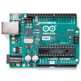
To develop this system , Arduino is used which is the heart of the water monitoring system. It is an open-source electronics platform which is based on a easily useable hardware as well as software. It a flexible and a cost-effective solution making electronics projects, robotic systems.
The Arduino comes in various sizes and different versions and models, but all of them have a microcontroller, input/output pins (analog and digital), and connectors used to interact with external devices. The Arduino is designed to be programmed easily and have a variety of compatible, communication modules, sensors and actuators.
programming and Arduino can be done using a Arduino software, Integrated Development Environment (IDE), a software tool which is very user-friendly. The IDE is a simplified version of the C++ programming language.
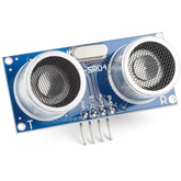
Other than the Arduino, a important part to the system is the ultrasonic sensor. The ultrasonic sensor is an electronic instrument used to measure the distance to a target. This is achieved by emitting a ultrasonic wave towards the object which then reflects the echoes of those waves into an electrical signal.
Ultrasonic sensors are used widely in water level monitoring systems because of the accuracy as well as the non-contact working capabilities. These sensors have a lot of application like, a tank monitoring or in a reservoir, irrigation systems and it has a few industrial applications etc.
read more : Arduino Uno Pin Diagram: A Complete Guide
UNDERSTANDING THE ULTRASONIC SENSOR:
An ultrasonic sensor is a device which uses sound waves which has a frequency of over the audible range of human to detect target objects and to measure the distances, or to monitor the liquid and solid level . The sensor consists of a transducer which emits a ultrasonic wave and it also consists of a receiver that can detect the reflected waves.
The ultrasonic sensor works on a common natural phenomenon known as ECHO of sound. A pulse is sent quickly, about 10us to trigger the sensors . After which it automatically sends 8 cycles of 40 KHz ultrasonic signals and it also checks the echo of sound. After striking with an obstacle it returns back and is caught by the receiver. Thus the distance between the obstacle and the sensor is calculated by the formula
Distance= (time x speed)/2.
read more : Interfacing GPS Module with Arduino
COMPONENTS REQUIRED
- ARDUINO UNO
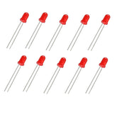
- LED
- HC SR04 ULTRASONIC SENSOR
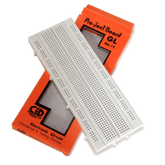
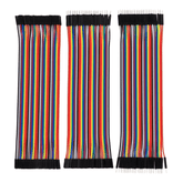
- BREADBOARD AND JUMPER WIRES
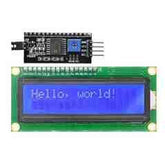
- 16x2 LCD (Blue) with I2C Interface
CIRCUIT DIAGRAM

an Arduino uno is used for easy use an 16x2 lcd with i2c interface is used . There are 4 pins in the lcd the ground is connected to the GND pin of the Arduino , the vcc is connected to the 5v pin of the Arduino , the SDA pin is connected to the the pin A4 of the Arduino and the SCL pin is connected to the pin A5 of the Arduino.
The ultrasound sensor connection to the Arduino is as follows, the GND and the VCC pin is connected along with the VCC and GND of the lcd to the Arduino’s GND and VCC. The TRIGGER is connected to the PIN 2 and the ECHO pin is connected to the PIN 3.
Here the SDA or the serial data pin and the SCL or serial clock pin is connected to the analog PIN A4 and analog PIN A5 whereas the ultrasound sensor’s TRIGGER and ECHO pin is connected to the digital PIN 2 & PIN 3 respectively
read our blog explaining arduino vs nodemcu, which provides a thorough comparison between Arduino Uno and NodeMCU microcontrollers.
ARDUINO PROGRAMMING
- First step towards is to install the Arduino software.
- After the installation, Connect the board: Use a USB cable to connect Arduino board to the computer. The software will detect the board automatically.
- Write your code: In the Arduino software, a text editor is present where we can write a code. programming is based on the C/C++ language, with a simple API and additional libraries.
- Once code is written, click the "Verify" button to check for any errors. If the code compiles successfully, click the "Upload" button to upload the code.
- Test your project: After uploading the code, run the program. You can monitor using the serial monitor to view output messages or debug the code.
Code structure
Header files initialized:
#include <Wire.h>
#include <LiquidCrystal_I2C.h>
(wire.h is a library that helps us communicate with i2c devices and The LiquidCrystal_I2C library allows us to program an Arduino to print messages to an LCD screen.)
Constants in the program:
const int trigPin = 2;
const int echoPin = 3;
LiquidCrystal_I2C lcd(0x27, 16, 2);
( first 2 lines of the snippet is constants for the ultrasonic sensor for the pins TRIGGER and echo the 3rd line is the constant for the LCD with I2C interface)
DECLARATIONS:
long duration;
int distance;
(duration is to calculate the duration of the echo pulse and distance is to find the distance between the point of contact and the release point)
INITIALIZATION:
void setup() {
pinMode(trigPin, OUTPUT);
pinMode(echoPin, INPUT);
lcd.begin(16, 2); // Initialize the LCD display
lcd.backlight(); // Turn on the backlight
lcd.setCursor(0, 0);
lcd.print("Water Level:");
Wire.begin();
}
MAIN PROGRAM:
void loop() {

  // Generate ultrasonic pulse

  digitalWrite(trigPin, LOW);

  delayMicroseconds(2);

  digitalWrite(trigPin, HIGH);

  delayMicroseconds(10);

  digitalWrite(trigPin, LOW);


  // Measure the duration of the echo pulse

  duration = pulseIn(echoPin, HIGH);


  // Calculate the distance in centimeters

  distance = duration * 0.034 / 2;


  // Print the distance on the LCD display

  lcd.setCursor(0, 1);

  lcd.print("                "); // Clear the previous reading

  lcd.setCursor(0, 1);

  lcd.print(distance);

  lcd.print(" cm");


  delay(1000); // Delay between measurements

}
COMPLETE CODE:
#include

#include


// Constants for ultrasonic sensor pins

const int trigPin = 2;

const int echoPin = 3;


// Constants for LCD display

LiquidCrystal_I2C lcd(0x27, 16, 2);


//constants for led

Const int led_pin=13;


// Variables

long duration;

int distance;

int waterthreshold=10;


void setup() {

  pinMode(trigPin, OUTPUT);

  pinMode(echoPin, INPUT);


  lcd.begin(16, 2); // Initialize the LCD display

  lcd.backlight(); // Turn on the backlight


  lcd.setCursor(0, 0);

  lcd.print("Water Level:");


  Wire.begin();

}


void loop() {

  // Generate ultrasonic pulse

  digitalWrite(trigPin, LOW);

  delayMicroseconds(2);

  digitalWrite(trigPin, HIGH);

  delayMicroseconds(10);

  digitalWrite(trigPin, LOW);


  // Measure the duration of the echo pulse

  duration = pulseIn(echoPin, HIGH);


  // Calculate the distance in centimeters

  distance = duration * 0.034 / 2;


  // Print the distance on the LCD display

  lcd.setCursor(0, 1);

  lcd.print("                "); // Clear the previous reading

  lcd.setCursor(0, 1);

  lcd.print(distance);

  lcd.print(" cm");

if(distance<=waterthreshold)

{

Digitalwrite(led_pin, LOW)

}

Else{

Digitalwrite(led_pin, HIGH)

}


  delay(1000); // Delay between measurements

}
TESTING AND CALIBRATION
To test and calibrate the water level monitoring system, follow these steps :
Hardware testing:
- Double-check all the connections and ensure if the wiring is correct .
- Upload the code to the Arduino and open the serial monitor to observe the distance readings from the ultrasonic sensor. Verify if the readings are changing as expected.
Calibration:
- Fill the water container water to different levels, starting from the lowest to the highest point.
- Note down the corresponding distance readings on the LCD display.
- Create a table for the distance readings and water levels
Verification:
- Test the system by changing the water level and verify if the distance readings and LED align with the calibration table.
- Check for any inconsistencies between the expected water levels and the measured levels. Adjust the calibration if necessary.
read more : Interfacing ACS712 with Arduino
COMMON ISSUES AND THE WAYS TO TROUBLESHOOT
Incorrect or unstable distance readings:
- Check that the ultrasonic sensor is connected to the Arduino and if it is powered.
- Check the wiring connections for any loose connections.
- Verify that the sensor is correctly positioned and it is facing the water.
- Calibrate the system to measure accurate distance.
- Check for any interference or noise sources that may affect the sensor readings.
Inconsistent behaviour of the LCD display:
- Confirm if the LCD connections are correct.
- Check the code for any errors.
- Ensure that the power supply to the LCD display is sufficient
- Verify the contrast adjustment for the LCD using the potentiometer.
- Test with different LCD display modules.
Communication issues with the LCD display (I2C):
- Check the I2C connections between the Arduino and LCD display.
- Confirm that the I2C address in the code matches the address of the LCD display.
- Ensure the I2C library is installed.
- Test with a different I2C LCD display
- Check for any conflicts with other devices using the I2C.
Top of Form
read more : Interfacing Proximity Sensors with Arduino
DATA VISULAIZATION
Data visualization tools like graphs can be plotted in the Arduino using the serial plotter. Serial plotter is a tool in Arduino IDE that can read data like temperature or humidity and it can also plot waveforms.
The steps to use serial plot:
Connect the Arduino to the pc via a usb cable.
Go to tools and select serial plotter.
Code:
Void setup()

{

Serial.begin(9600);

}

Void loop()

{

serial.print(duration);

  serial.print(" ");

  serial.print(distance);

delay(1000);

}
PRACTICAL APPLICATIONS
This simple arduino uno project can be implemented in a larger scale like houses to check the water levels in the tank.
It can also be used in dams and water reservoir to see if it crosses the threshold and to check the amount of water in large places like this.
it is also an excellent arduino uno project for beginners.
The system can be used in agricultural settings to monitor water levels in irrigation systems or tanks. resources, optimize irrigation schedules, and prevent overwatering or water shortages in crops.
The system can be used in environmental monitoring such as rivers, lakes.
read more : How to use Buzzer with Arduino
CONCLUSION
The Arduino-based water level monitoring system gives a practical and cost-effective solution for monitoring water. With the combination of an Arduino, ultrasonic sensor, and an LCD display, this system offers several advantages. The affordability, ease of installation, and flexibility makes it accessible to a wide range of users.
The real-time monitoring capability of the system, The accuracy and precision of the ultrasonic sensor ensures reliable water level measurements. The non-contact measurement feature of the ultrasonic sensor eliminates the need for physical contact
Therefore, The Arduino-based water level monitoring system can be used in various fields like agriculture, environmental monitoring and home automation.
If you appreciate our work don't forget to share this post and leave your opinion in the comment box.
Please do check out other blog posts about Popular electronics
Make sure you check out our wide range of products and collections (we offer some exciting deals!)
Frequently Asked Questions
1. How do you monitor water level with Arduino?
Monitoring water levels using an Arduino involves utilizing sensors to detect the water's height and then translating that data into a readable form, often through LEDs, displays, or even remote notifications. In the context of the webpage you provided, there's information about using various sensors and components to achieve this. Here's a general approach to monitor water levels with an Arduino:
1. Choose a Water Level Sensor:
There are several types of water level sensors available, such as float sensors, ultrasonic sensors, capacitive sensors, and more. These sensors detect the water level based on changes in physical properties when in contact with water.
2. Connect the Sensor to Arduino:
Connect the chosen water level sensor to the appropriate pins on the Arduino board. The sensor's datasheet or documentation will guide you on how to connect the sensor's output to the Arduino's input pins.
3. Read Sensor Data:
Depending on the type of sensor, you might read analog or digital data. Analog sensors provide varying voltage levels, while digital sensors provide simple on/off signals. Use the Arduino's analog or digital input pins to read the data from the sensor.
4. Calibrate the Sensor:
Calibrating the sensor ensures accurate readings. This might involve setting a baseline reading when the water level is at a known point (empty or full), and then mapping the sensor's output values accordingly.
5. Interpret Sensor Data:
Translate the raw data from the sensor into meaningful information about the water level. For example, if using LEDs, you could light up different LEDs corresponding to different water levels.
6. Display or Alert:
Use the data interpretation to display the water level information. This could be through LEDs, an LCD display, or even sending notifications to a computer or smartphone via Wi-Fi or GSM module, as mentioned in some of the search results you provided.
7. Implement Safety Measures (Optional):
Depending on the application, you might want to include safety measures, such as triggering an alarm or shutting off a pump when the water level reaches critical points.
8. Power Supply:
Ensure that the Arduino and the sensor are powered appropriately. In some cases, you might need to consider power-saving techniques to prolong battery life.
Remember that the specific steps will vary based on the sensor you're using and your project's requirements. The webpage snippets you've shared discuss various types of water level sensors and how to interface them with Arduino to monitor and control water levels. Always refer to the datasheets and documentation of the sensors you're using for accurate connections and programming details.
read more : How do I Power my Arduino?
2. Can Arduino ultrasonic sensor detect water?
Yes, Arduino ultrasonic sensors can be used to detect the level of water. Ultrasonic sensors work based on the principle of sending out ultrasonic waves and measuring the time it takes for the waves to bounce back after hitting an object. When these sensors are used to detect water levels, the ultrasonic waves are sent towards the water surface, and the sensor measures the time it takes for the waves to reflect back from the water surface.
read more : Difference Between Arduino and Raspberry Pi
There are several types of water level sensors available, such as float sensors, ultrasonic sensors, capacitive sensors, and more. These sensors detect the water level based on changes in physical properties when in contact with water.
Connect the chosen water level sensor to the appropriate pins on the Arduino board. The sensor's datasheet or documentation will guide you on how to connect the sensor's output to the Arduino's input pins.
Depending on the type of sensor, you might read analog or digital data. Analog sensors provide varying voltage levels, while digital sensors provide simple on/off signals. Use the Arduino's analog or digital input pins to read the data from the sensor.
Calibrating the sensor ensures accurate readings. This might involve setting a baseline reading when the water level is at a known point (empty or full), and then mapping the sensor's output values accordingly.
Translate the raw data from the sensor into meaningful information about the water level. For example, if using LEDs, you could light up different LEDs corresponding to different water levels.
Use the data interpretation to display the water level information. This could be through LEDs, an LCD display, or even sending notifications to a computer or smartphone via Wi-Fi or GSM module, as mentioned in some of the search results you provided.
Depending on the application, you might want to include safety measures, such as triggering an alarm or shutting off a pump when the water level reaches critical points.
Ensure that the Arduino and the sensor are powered appropriately. In some cases, you might need to consider power-saving techniques to prolong battery life.


