RF 433 MHZ TRANSMITTER AND RECEIVER (WITH DEMO)
Gone are those days when we had to lay cables and put them through walls etc. Now, we live in an era where everything is wireless. What if I say that you can control home appliances, open the garage door and monitor the health of patients remotely without the hassle of connecting too many wires. Don’t you find it cool and exciting? Presenting to you the RF module!
Why RF Communication?
Security is critical for many applications - from garage door openers to IoT devices. Trust an RF interface for your application, because it is harder to hack. Unlike other communications, it doesn’t require a line-of-sight operation. Its range of communication is much better around 502 feet and more importantly, it is cost-effective.
Several carrier frequencies are commonly used in commercially available RF modules such as 433MHz/434MHz, 915MHz, and 2400MHz.
Here we’ll see about the RF 433MHz transmitter and receiver.
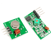
RF 433 MHz Transmitter
An RF transmitter module is a small PCB sub-assembly capable of transmitting a radio wave and modulating that wave to carry data. Transmitter modules are usually implemented alongside a microcontroller which will provide data to the module which can be transmitted. RF transmitters are usually subject to regulatory requirements which dictate the maximum allowable transmitter power output, harmonics, and band edge requirements.
RF 433 MHz Receiver
An RF receiver module receives the modulated RF signal and demodulates it. There are two types of RF receiver modules: superheterodyne receivers and super-regenerative receivers. Super regenerative modules are usually low-cost and low-power designs. It uses a series of amplifiers to extract modulated data from a carrier wave. Super-regenerative modules are generally imprecise as their frequency of operation varies considerably with temperature and power supply voltage.
Superheterodyne receivers have a performance advantage over super-regenerative; they offer increased accuracy and stability over a large voltage and temperature range. This stability comes from a fixed crystal design which in the past tended to mean a comparatively more expensive product. However, advances in receiver chip design now mean that currently there is little price difference between superheterodyne and super-regenerative receiver modules.
RF 433 MHz Receiver and Transmitter with Arduino Components Required:
• 2 Arduino boards
• RF 433 MHz receiver-transmitter pair
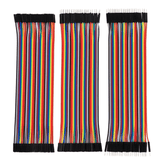
• Jumper wires
• 2 LEDs
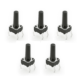
• Push button
• Resistor(220 ohm)
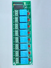
• Relay
• Buzzer
Connections:
RF Transmitter
The connection for the RF Transmitter Module is very simple. It consists of 4 pins: VCC, GND, Data and Antenna. VCC and GND pins are connected to 5V and ground respectively. The data pin is connected to any of the digital input/output pins of Arduino. Here, it is connected to Pin 12. A switch is connected to Pin 3 and GND and a resistor (220 ohms) is connected to Pin 3 and GND as shown. We are using an external LED connected to Pin 13 for demonstration.
Transmitter Code:
#include <VirtualWire.h>
int inPin = 3;
int outPin = 13;
char *data;
int state = HIGH;
int reading;
int previous = LOW;
long time = 0;
long debounce = 200;
void setup()
{
pinMode(inPin,INPUT_PULLUP);
pinMode(outPin, OUTPUT);
vw_set_ptt_inverted(true);
vw_set_tx_pin(12);
vw_setup(2000);
}
void loop()
{
reading = digitalRead(inPin);
if (reading == HIGH && previous == LOW && millis() - time > debounce)
{
if (state == HIGH)
{
state = LOW;
data="0";
vw_send((uint8_t *)data, strlen(data));
vw_wait_tx();
}
else
{
state = HIGH;
data="1";
vw_send((uint8_t *)data,strlen(data));
vw_wait_tx();
time = millis();
}
}
digitalWrite(outPin, state);
previous = reading;
}
RF Receiver
The RF Receiver Module also consists of 4 pins: VCC, GND, Data, and Antenna. VCC and GND pins are connected to the 5V pin of the Arduino and ground respectively. The data pin is connected to Pin 12 of the Arduino. The relay consists of 3-pins: I/P, VCC, and GND. The input is connected to Pin 2, VCC, and GND to the 5V pin and ground pin of Arduino, respectively. A buzzer is connected to 5V and GND and is controlled by the relay as shown. LED, connected to pin 13, is used for demonstration as shown.
Receiver Code:
#include<VirtualWire.h>
const int ledPin = 13;
const int datain = 12;
int relayPin1 = 2;
void setup()
{
Serial.begin(9600);
vw_set_ptt_inverted(true);
vw_set_rx_pin(datain);
vw_setup(2000);
pinMode(ledPin, OUTPUT);
vw_rx_start();
pinMode(relayPin1, OUTPUT);
}
void loop()
{
uint8_t buf[VW_MAX_MESSAGE_LEN];
uint8_t buflen = VW_MAX_MESSAGE_LEN;
if (vw_get_message(buf, &buflen))
{
Serial.print(buf[0]);
if(buf[0]=='1')
{
digitalWrite(ledPin,HIGH);
Serial.print(buf[0]);
digitalWrite(relayPin1, HIGH);
}
if(buf[0]=='0')
{
digitalWrite(ledPin,LOW);
Serial.print(buf[0]);
digitalWrite(relayPin1,LOW);
}
}
}
Working Process:
In this project, a simple demonstration of RF Communication with the help of Arduino UNO boards is given. The aim of the project is to successfully transmit data between the RF Transmitter – Receiver modules using two Arduino UNO microcontroller boards and switching on/off a component on the receiver side through transmitted data. The working of the project is explained here.
“VirtualWire.h '' is a special library for Arduino created by Mike McCauley. It is a communication library that allows two Arduino to communicate with each other using the RF Module i.e. transmitter-receiver pair. This library consists of several functions that are used for configuring the modules, transmission of data by the transmitter module and data reception by the receiver module. In this project, the transmitter simply sends two characters i.e. it sends the character “1” and “0” controlled by a push button. Here the push button is acting as a switch. The initial state of the switch is high. When we press it, data ‘0’ is transmitted via RF communication and the receiver will
receive the data “0”. Relay here is switched off. When again the switch is pressed data “1” is transmitted and the same will be received on the receiver side. Whenever “1” is received LED and relay are turned ON. Buzzer connected to the relay starts making a sound.
Here, basically, we are transmitting data and controlling components connected to the receiver side using a switch.
Excerpt
Frequently Asked Questions
1. What is an RF 433 MHz transmitter and receiver module used for?
An RF 433 MHz transmitter and receiver module are primarily used for wireless communication in DIY electronics projects. They enable remote control and data transmission between devices without cables. Common applications include home automation systems, alarm systems, and wireless sensor networks, making them popular for hobbyists and professionals alike.
2. How do you wire an RF 433 MHz transmitter to Arduino?
To wire an RF 433 MHz transmitter to an Arduino, connect the data pin of the transmitter to a digital pin on the Arduino (e.g., pin 12). Connect the VCC pin to the Arduino's 5V and the GND pin to its ground. This setup allows the Arduino to send signals wirelessly using simple code.
3. How do you wire an RF 433 MHz receiver to Arduino?
To wire an RF 433 MHz receiver to an Arduino, connect the data pin of the receiver to a digital pin on the Arduino (e.g., pin 11). Connect the VCC pin to the Arduino's 5V and the GND pin to its ground. This configuration enables the Arduino to receive wireless signals and process them accordingly.
4. What code libraries support RF modules on Arduino?
Several code libraries support RF modules on Arduino, most notably the "VirtualWire" and "RadioHead" libraries. These libraries simplify wireless communication using RF modules. They provide functions for sending and receiving messages, making it easier for users to integrate RF functionality into their projects.
5. What is the range of a 433 MHz RF module in DIY projects?
The typical range of a 433 MHz RF module in DIY projects is approximately 30 to 100 meters, depending on environmental factors like obstacles and interference. In open spaces, a clear line-of-sight can extend this range significantly. However, performance may vary based on the specific module and setup used.
6. What types of wireless projects can you build with RF modules?
RF modules can be used to build various wireless projects, including remote-controlled cars, weather stations, home automation systems, and wireless sensor networks. They’re ideal for transmitting data between devices in a straightforward manner, making them versatile for hobbyists and DIY enthusiasts.
7. Are 433 MHz RF modules safe for use and legal in India?
Yes, 433 MHz RF modules are generally considered safe for use and are legal in India. They operate in the ISM band, which is designated for unlicensed use. However, it's essential to ensure compliance with local regulations regarding transmission power and usage to avoid interference with other devices.
8. What are the limitations of RF 433 MHz modules compared to WiFi or Bluetooth?
RF 433 MHz modules offer limited data rates and range compared to WiFi and Bluetooth. While they excel in low-power applications, their bandwidth is much lower, typically around 1-10 kbps. Additionally, they lack the advanced security features found in WiFi and Bluetooth, making them less suitable for high-security applications.
9. How to troubleshoot when RF receiver doesn’t pick up signals?
If the RF receiver isn’t picking up signals, check the wiring for correct connections and ensure the transmitter is powered on. Confirm that both devices operate on the same frequency and are within range. Additionally, assess if any obstacles may be interfering with the signal and try changing the environment.
10. Can you use multiple RF transmitters and receivers for remote control?
Yes, you can use multiple RF transmitters and receivers for remote control applications. By assigning unique identifiers to each transmitter, you can control various devices individually. This setup allows for flexible project designs and enhances the functionality of your wireless systems.


