Controlling an LED with Two ESP32s: A Step-by-Step Guide
Summary
Using two ESP32 microcontrollers to control an LED remotely is a fantastic way to demonstrate their communication capabilities. In this guide, we'll explore how to set up one ESP32 as a server to control an LED connected to a second ESP32 acting as a client. We'll cover both Wi-Fi and Bluetooth communication methods.
Episode EE03:

Read this blog ALL YOU NEED TO KNOW ABOUT ESP32
What You’ll Need
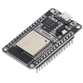
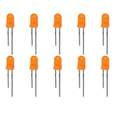
Two ESP32 Boards: One for controlling the LED (Server) and one for sending control commands (Client).- LED: For demonstration.
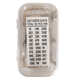
- Resistor: 220Ω to 330Ω to limit the current to the LED.
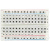
- Breadboard and Jumper Wires: For connections.
- USB Cables: For programming the ESP32 boards.
- Arduino IDE: For coding and uploading to the ESP32 boards.
Do you know How to connect esp32 to wifi - Read now!
Wi-Fi Communication (Client-Server Model):
Setup ESP32 as a Server (LED Controller)
1. Circuit Diagram
The image shows the LED connected to the ESP32 via a resistor.
- LED Anode (long leg) to GPIO 2 (or any other GPIO) on ESP32.
- LED Cathode (short leg) to GND via a 220Ω resistor.

2. Code for ESP32 Server:
#include
// Replace with your network credentials
const char* ssid = "YOUR_SSID";
const char* password = "YOUR_PASSWORD";
WiFiServer server(80);
const int ledPin = 2; // LED connected to GPIO 2
void setup() {
Serial.begin(115200);
WiFi.begin(ssid, password);
while (WiFi.status() != WL_CONNECTED) {
delay(500);
Serial.print(".");
}
Serial.println("Connected to WiFi");
server.begin();
pinMode(ledPin, OUTPUT);
digitalWrite(ledPin, LOW); // Make sure LED is off initially
}
void loop() {
WiFiClient client = server.available();
if (client) {
String request = client.readStringUntil('\r');
client.flush();
if (request.indexOf("/LED_ON") != -1) {
digitalWrite(ledPin, HIGH);
}
if (request.indexOf("/LED_OFF") != -1) {
digitalWrite(ledPin, LOW);
}
client.print("HTTP/1.1 200 OK\r\nContent-Type: text/html\r\n\r\n");
client.print("\r\n\r\n");
client.print("\r\n");
client.print("\r\n");
client.print("\r\n");
client.print("\r\n\r\n");
client.stop();
}
}
3. Explanation:
The ESP32 server listens for HTTP requests. When it receives a request containing /LED_ON or /LED_OFF, it controls the LED connected to GPIO 2 accordingly.
4. Upload the Code and Test:
- Upload the code to the ESP32 server.
- Open the Serial Monitor to find the IP address of the ESP32.
- Enter the IP address in a web browser. Use the provided links to control the LED.
Learn how to build a Smart water quality monitoring system using ESP32
Setup ESP32 as a Client (Control Sender)
Code for ESP32 Client:
#include

// Replace with your network credentials and server IP
const char* ssid = "YOUR_SSID";
const char* password = "YOUR_PASSWORD";
const char* serverIP = "SERVER_IP_ADDRESS"; // Replace with the server's IP address

void setup() {
  Serial.begin(115200);
  WiFi.begin(ssid, password);

  while (WiFi.status() != WL_CONNECTED) {
    delay(500);
    Serial.print(".");
  }
  Serial.println("Connected to WiFi");
}

void loop() {
  WiFiClient client;
  if (client.connect(serverIP, 80)) {
    client.println("GET /LED_ON HTTP/1.1");
    client.println("Host: " + String(serverIP));
    client.println("Connection: close");
    client.println();

    delay(10000); // Wait 10 seconds before sending another request

    client.println("GET /LED_OFF HTTP/1.1");
    client.println("Host: " + String(serverIP));
    client.println("Connection: close");
    client.println();
  }
  delay(10000); // Wait 10 seconds before reconnecting
}
Explanation:
The ESP32 client sends HTTP GET requests to the server to turn the LED on and off periodically.
Also read: How to interfaceDS18B20 Temperature Sensor with ESP32
Conclusion
Controlling an LED with two ESP32 boards can be achieved using various communication methods, including Wi-Fi and Bluetooth. By following the steps outlined above, you can set up a server-client model over Wi-Fi or use Bluetooth serial communication to control your LED. These methods can be extended to more complex applications and integrated into larger IoT systems. Happy experimenting!
Please do check out other blog posts about Popular electronics
Check out other related blog posts about Drones: Drone transmitter and receiver , Drone motors and Getting started with a Quadcopter
Make sure you check out our wide range of products and collections (we offer some exciting deals!)


