


introduction
This Line Follower Robot Using Arduino is an innovative robotic platform that allows users to program and customize their own robots. The robot is simple to assemble, requires minimal programming experience, and can be adapted for a wide range of applications including navigation between two points or following shapes like circles on the floor. It uses infrared sensors mounted beneath its body which detect black lines against light surfaces such as white tiles – allowing it to track pre-programmed paths with ease! With this high quality solution from Arduino, creating your perfect line follower has never been easier.

read more : Interfacing Proximity Sensors with Arduino
Working of Line Follower Robot
Line Follower Robot is a robotic device that has the capability to detect and track a line drawn on the ground. It can follow any type of surface, including straight or curved lines drawn directly onto surfaces such as drywall, carpets, wood floors and more. With advanced programming features built into its board logic circuit along with an Arduino microcontroller-based platform utilized for controlling input/output operations of sensors related components like motor drivers for motion control; it autonomously tracks paths regardless of size or shape accurately in real time.
Using fancy algorithms integrated within Line Followers' system design allows them to utilize light detection technique through various implementations like Photoresistor Arrays paired with Light Sensors programmed accordingly depending upon application requirements by providing direction information based off contrast between two different patterns given by black following white indicating left turns while vice versa being right turn indications or other labelled signals (e.g mirrors). These robots also come equipped powerful motors processing object proximity data further allowing their navigations at high speeds without obstruction incidents sans human intervention process exploiting wireless technologies such as Bluetooth enabling remote smartphone access via dedicated App which adds flexibility & portability layer making whole experience even smoother.
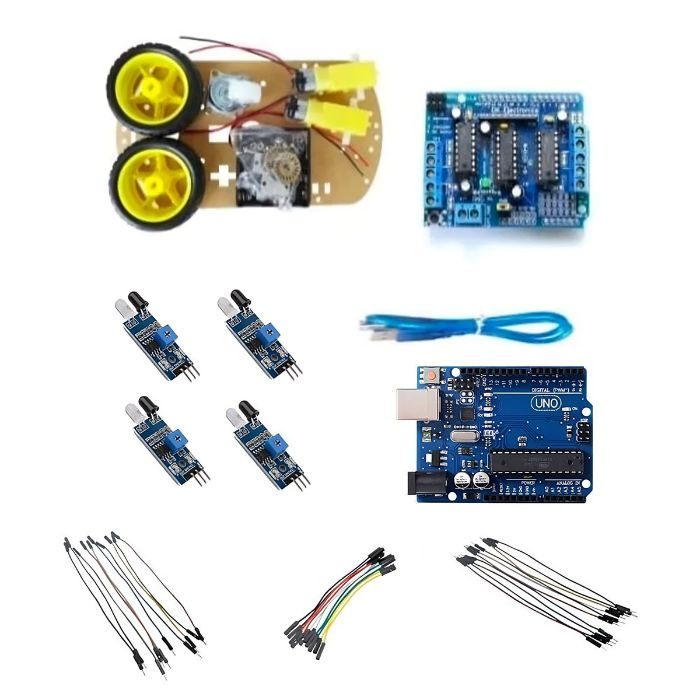
Components Required
- Arduino Uno (with cable)
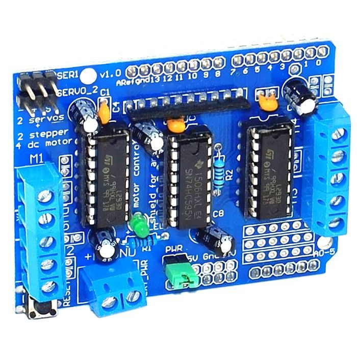
- L293D Motor Driver Shield for Arduino
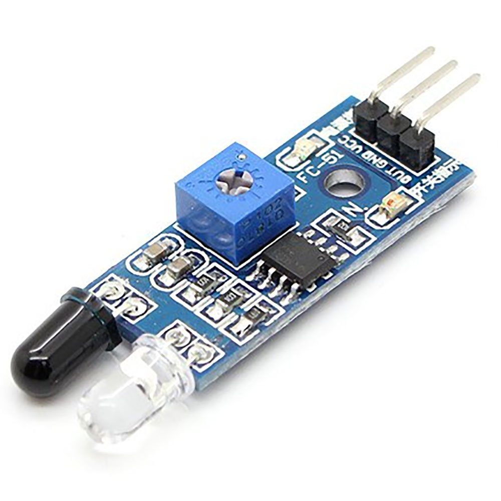
- Range adjustable IR sensor (x4)
- Baseboard (x1)
- Encoder disc (x2)
- Deceleration DC Motors (x2)
- Battery container (x1)
- Wheels (x2)
- Hammer castor (x1)
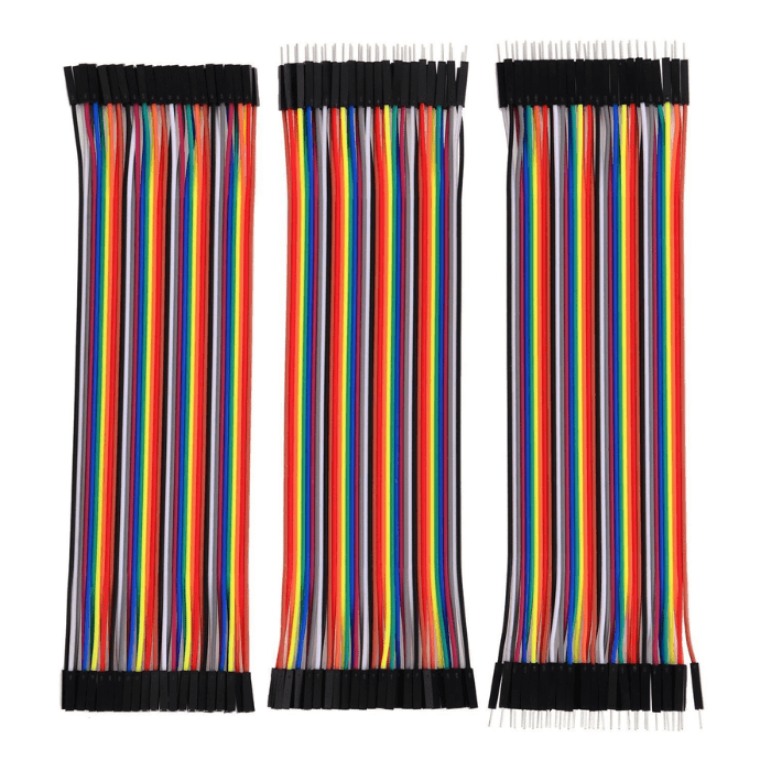
- Jumper wires: male-to-male|male-to-female|female-to-female (x10)
- Switch (x1)
- Spacers (x4)
- Fasteners (x4)
- M3*30 screw (x4)
- M3*8 screw (x20)
- M3 nut (x18)
- L12 spacer (x4)
read more : LED Interfacing with Arduino
Assembling

We start off by the assembly of the two-wheeled drive DIY kit. We first connect the motors to the board by putting the fastener in the given slots and tightening them with M3*30 screws. Now, the wheels can be attached to the motors. Besides the two wheels, we are also provided with a hammer castor wheel which serves to support the motion of the robot by following the other two wheels while in motion.

The castor wheel is attached along with the spacers provided, this maintains the height of the castor and keeps the robot in a fixed horizontal plane. Now that all the moving parts are taken care of, we come to the power supply which is provided with the help of 4 AA batteries.
The battery container for the same is also provided with the DIY kit, it can be attached on the top. Note that the AA batteries are not necessarily the only power source to be used, we can use a 9V battery as well. If you have worked on with Arduino and motors, it will be conspicuous in your that using either 4 AA batteries or one 9V battery won’t last long. What can be done better is using the 9V battery to supply power to Arduino and the AA batteries for the motor driver, or you can use some good current rating AA batteries only.
So, by now, we have one easily assembled two-wheel drive robot. We now come to the electronics part. Take the Arduino and screw it to the baseboard (or you can use a double-sided tape as well). When done, attach the L293D Motor Driver Shield on the top of Arduino, making sure that corresponding pins in both are correctly connected. Take two wires each from both the motors and connect them to the motor driver shield placed on Arduino (say, M1 and M2).
Check the connections for the same direction of motors as opposite polarity can cause counter motions. Now, we will shift our focus to the IR sensors which we place in the front. Two of them are used and both try to make bot move in such a way that the line it is traveling on is always in between the two. Connect the 5V and GND pins of the sensors to the 5V and GND points given in the shield. The input signal from the IR sensors is given through the Analog pins (here, we have used A0 and A1).
Through the serial monitor on Arduino IDE, we check the values of IR sensors when on the line and when not on the line. And, accordingly, we write a code with ‘if-else’ statements to make the bot move forward or turn left/right. The libraries for the motor driver shield can be downloaded online or directly go to this download URL: https://goo.gl/fScTIj . Include the libraries for the DC motors, define an object for each and also declare pins for the sensor. You can see the complete program below:
read more : Interfacing ACS712 with Arduino
Check out the video for step by step assembling instructions:
Code
// Line-follower Robot using Arduino Uno and Motor Shield
// library for DC motor #include
// defining the two motors
AF_DCMotor motor1(1, MOTOR12_64KHZ);
AF_DCMotor motor2(2, MOTOR12_64KHZ);
// declaring Sensor Pins.
int LeftSensor = A0;
int RightSensor = A1;
int L_sensor_val = 0; // To store value from sensors.
int R_sensor_val = 0;
int threshold = 500;
void setup() {
}
void loop() {
motor1.setSpeed(150);
motor2.setSpeed(150);
// set the speed to 200/255
L_sensor_val = analogRead(LeftSensor); // Reading Left sensor data R_sensor_val = analogRead(RightSensor); // Reading Right sensor data
if (L_sensor_val>threshold && R_sensor_val>threshold) {
}
motor1.run(FORWARD);
motor2.run(FORWARD);
if (L_sensor_valthreshold) {
}
motor1.run(BACKWARD);
motor2.run(FORWARD);
}

}
After uploading the code, if your bot is not running in the right direction, then change the wiring of BO motors. Also, calibrate both IR sensors by varying their potentiometer.
The speed of the motor can be varied according to the requirement and the accuracy required and, similarly, the IR sensor values can also vary depending on the color of the path and can be utilized for multiple purposes.
read more : How NRF24l01 Arduino Nano Works
Conclusion
Diving into the world of robotics through the DIY Line Follower Kit using Arduino offers an exhilarating journey from inception to creation. By understanding the intricate working of the line follower robot, assembling the components with care, and crafting the code to guide its path, you've embarked on a hands-on learning adventure that blends technology and innovation. With this newfound knowledge, you're now equipped to explore endless possibilities in robotics and automation. So, what are you waiting for? Unleash your creativity and embark on your own robotics odyssey today!