Skip to product information
1 of 4

Robocraze

MCP2515 Can Bus Module Board TJA1050 Receiver SPI for 51 MCU Arm Controller

MCP2515 Can Bus Module Board TJA1050 Receiver SPI for 51 MCU Arm Controller

Regular price Rs. 121
Regular price Rs. 199 Sale price Rs. 121
Sale Sold out 39% off Best Price Guaranteed
You save Rs. 78 | Free Shipping on Orders Above ₹ 499/-
Incl. GST (No Hidden Charges)
Currently, people are actively viewing.
Product will be SHIPPED TODAY, if ordered within 14 hours and 42 minutes.

BEST COUPON FOR YOU

FLAT ₹ 100/- OFF RC100

When you shop for ₹ 2500 or more.Applicable on Checkout.

*Coupons are not applicable on Original Boards and Kits

Submit your Bulk Enquiry Here
  • The MCP2515 CAN bus module supports CAN 2.0B protocol.
  • It uses High-speed CAN transceiver TJA1050
  • The MCP2515 CAN bus has SPI control for expanding Multi CAN bus interface.
  • It features a serail port to view communication data.
  • It comes with a power indicator and a LED indicator.
Trust Badge 1 Trust Badge 2 Trust Badge 3

MCP2515 Can Bus Module Board

Controlled Area Network of simple CAN is a bus standard that allows a Microcontroller and its peripheral devices to communicate without the need of a host device or a computer. The MCP2515 CAN bus module is designed with an SPI 51 Single Chip Program and features a TJA1050 Receiver. It is created to control a CAN Bus device by SPI interface with your MCU. It is best used by microcontrollers and boards compatible with Arduino like UNO boards. 

The MCP2515 CAN Bus Controller is a simple Module that supports CAN Protocol version 2.0B and can be used for communication at 1Mbps. In order to set up a complete communication system, you will need two CAN Bus modules.

The MCP2515 CAN bus module consists of standard frames, extended frames, and remote frames. You can use the serial port of the  MCP2515 CAN bus module to view communication data as well. 
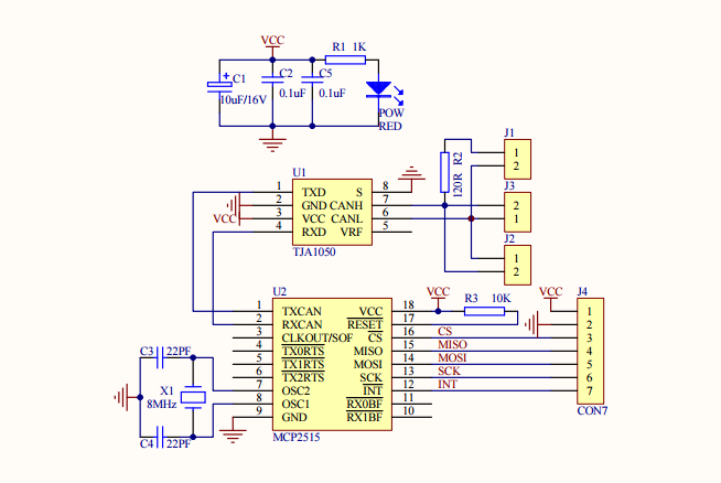
Pin Details

  • VCC :5V power input pin
  • GND : power ground pin
  • CS : SPI SLAVE select pin (Active low)
  • SO : SPI master input slave output lead
  • SI : SPI master output slave input lead
  • SCLK: SPI clock pin
  • INT: MCP2515 interrupt pin

Pin Diagram:

Pin Diagram of MCP2515 Can Bus Module Board

Applications:

  • Electronic Gear Shift System
  • Automobiles
  • Main Interface in Automation (like industrial)
  • Medical Equipment
  • Robotics
  • Auto Start/Stop of Car Engine

Package Includes:

  • 1 x MCP2515 Can Bus Module Board TJA1050 Receiver SPI for 51 MCU Arm Controller

Specifications:

Model  MCP2515 Can Bus Module Board
Transceiver Used  High Speed CAN TJA1050
Oscillator Used  8MHZ crystal oscillator
Resistance 120Ω terminal resistance
Data Field Type  0 to 8 bytes long data field
Dimensions 4 x 3 x 1 cms
Weight 0.5 grams

Shipping & Returns

  • All orders confirmed before 3 pm IST are shipped on the
    same day, barring rare pickup delays on holidays or disturbances
  • Delivery time in Metro cities is 1-3 days, Others it is
    3-7 days. It varies based on location, reliant on courier services
  • Return window: 7 days from receipt unless stated
    otherwise. No refunds/replacements after
  • Returns only for non-working/damaged products are accepted
  • Initiate return requests to our customer service team via Support ticket or contact us at +91-8123057137
  • Refunds are processed within 3-4 working days post inspection and approval.

For more details, please check our Shipping and Return Policy

View full details
Trust Badge 1 Trust Badge 2 Trust Badge 3

Found a better price?

Let us know!
We'll try to match the price for you

  • ⚡ Dispatched within 24 hours

  • 💰 Earn RC Coins on every purchase

  • 🚚 Free shipping on orders above Rs 500/-

  • 🛠️ Dedicated Technical Support Team

1 of 4

1. What is the XL6009 boost module? Where is it used?

  • The XL6009 boost module is a non-isolated step-up boost voltage converter featuring adjustable output voltage and high efficiency. It converts an input voltage of 5-32V DC to an output voltage of 4-38V DC. The XL6009 boost module is used mainly used in Solar Cell, Car Regulator, and Wind Power

2. How do I use the step-up XL6009 boost module?

  • The XL6009 Step Up Down module is an automatic Buck-Boost Converter. And as a result, the output voltage of the module can be fixed at a specific voltage, and the input can be higher or lower than the output voltage. The power module has a potentiometer to adjust the output voltage according to the user needs. Users can adjust the potentiometer to get the output voltage from 5V to 35V. However, the higher input voltage offers higher load current capabilities. The interfacing of the XL6009 module is quite easy. 
    • Connect the regulated or unregulated input across the IN+ and IN- pin and use the potentiometer to adjust the output voltage.
    • Connect the load directly at OUT+ and OUT- pins.

3. What are the advantages of the XL6009 boost module?

  • Below are the advantages of the XL6009 boost module
    • Gives a high output voltage.
    • Low operating duty cycles.
    • The lower voltage on MOSFET.

4. What is the difference between buck and boost converter?

  • The buck converter is a voltage step-down converter, and the boost converter is a voltage step-up converter. The voltage transformation ratio depends on the source voltage and the required load voltage.