Sending data from Arduino nano to Raspberry Pi using lora communication
Summary
Discover the seamless world of wireless data transfer with LoRa communication as we delve into a captivating journey in this blog. Starting with an introduction to the concept, we explore the power of Arduino Nano as the data sender. Unravel the magic of LoRa-enabled devices with our detailed sender program guide. Uniting the Arduino Nano and Raspberry Pi, we unleash the full potential of data transmission. Join us in exploring the wonders of LoRa communication and how it bridges the gap between these two powerful devices. Get ready to embark on a thrilling tech adventure!
Introduction:
In this tutorial, we will learn how to connect the LORA Module to the Arduino Nano and Raspberry Pi. We will use the Raspberry Pi, Arduino Nano, and Lora to create a transmitter and receiver for data transmission and reception respectively. The tutorial will provide step-by-step instructions on how to connect the LORA Module to the Arduino Nano and Raspberry Pi. It will explain how to use these components to create a transmitter and receiver for data transmission and reception.
Arduino nano:
STEP 1(Hardware connection):
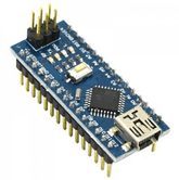
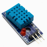
Let us first setup the transmitter part first. The transmitter part contains Arduino Nano Board, DHT11 Humidity & Temperature Sensor and LoRa Module. Assemble the connection between Arduino nano and DHT sensor as shown in the table below:
|
Arduino nano |
DHT11 Sensor |
|
5 v |
VCC |
|
GND |
GND |
|
Digital Pin 7 |
Out |
And the connection between Lora and Arduino Nano:
|
Lora module |
Arduino nano |
|
2,3,4,5,6,7,8,9 (8 Pin connector) |
Keypad connector (2,3,4,5,6,7,8,9) |
|
4 Pin connector (G, 5V, 10, 11) |
4 Pin connector (G, 5V, 10, 11) |
|
4 Pin connector (G, 5V, 12, 13) |
4 Pin connector (G, 5V, 12, 13) |
Explore the versatility of Arduino Nano in one blog!
STEP 2(downloading the libraries):
Connect your Arduino nano with DHT11 Sensor. For DHT11 sensor, install the dht library and for send the sensor readings to Raspberry Pi, install the lora library using the Library Manager in the Arduino IDE. Go to Sketch > Include Library > Manage Libraries and search for library name in the library manager.

STEP 3 (Explanation of the program):
Explanation:
Including the necessary libraries: We include the required libraries, such as LoRa, SPI, and DHT (for the DHT11 sensor).
Defining the constant: The code defines the type and digital pin of DHT sensor and define the required frequency for the Lora module. The ss, rst, and dio0 are the pin numbers used by the LoRa transceiver module that is connected to Arduino nano pin 10, 9, 2.
Create necessary objects: It defines the DHT sensor object called dht.
Setup Function: The setup function initializes the serial communication, the DHT sensor and the Lora module. It set the pin for lora transceiver using setPins() function. The code waits until LoRa initialization is successful before printing a confirmation message.
Loop Function: The loop function reads the temperature and humidity values from the DHT sensor. Then it prints these values to the serial monitor. After that, it starts a LoRa packet, writes the temperature and humidity values to the packet, and ends the packet transmission.
Sender program:
#include

#include

#include


#define LORA_FREQUENCY 868E6

#define DHTPIN 7 // Digital pin connected to the DHT sensor

#define DHTTYPE DHT11 //DHT sensor type

DHT dht(DHTPIN, DHTTYPE);


//define the pins used by the transceiver module

#define ss 10

#define rst 9

#define dio0 2


void setup() {

  Serial.begin(115200);

  dht.begin();

  while (!Serial);

  Serial.println("LoRa Sender");


  //setup LoRa transceiver module

  LoRa.setPins(ss, rst, dio0);

  while (!LoRa.begin(LORA_FREQUENCY)) {

    Serial.println(".");

    delay(500);

  }

  Serial.println("LoRa Initializing OK!");

}


void loop() {

  float temperature = dht.readTemperature();

  float humidity = dht.readHumidity();


  Serial.print("Temperature: ");

  Serial.print(temperature, 2);

  Serial.print("\t Humidity: ");

  Serial.println(humidity, 2);


  LoRa.beginPacket();

  LoRa.print("Temperature: ");

  LoRa.print(temperature);

  LoRa.print("\t Humidity: ");

  LoRa.print(humidity);

  LoRa.endPacket();

  delay(1000);

}
Raspberry Pi:
STEP 1(Hardware connection):
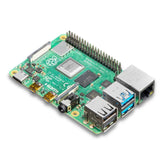
Let us setup the Receiver part. Assemble the connection between Raspberry Pi and Lora as shown in the table below:
|
Lora module |
Raspberry Pi |
|
2,3,4,5,6,7,8,9 (8 Pin connector) |
Keypad connector (2,3,4,5,6,7,8,9) |
|
4 Pin connector (G, 5V, 10, 11) |
4 Pin connector (G, 5V, 10, 11) |
STEP 2(Install the library):
For lora communication we need to Install wiringPi library:
You'll need git. If git is not installed, enter the following into the command line.
sudo apt-get install git-core
We highly recommend using Git to download the latest version. To check the version of wiringPi, enter the following command.
gpio -v
If you receive an output similar to the following with the Unknown17, you'll want to update WiringPi on a Raspberry Pi 4 or above.
gpio version: 2.50
Copyright (c) 2012-2018 Gordon Henderson
This is free software with ABSOLUTELY NO WARRANTY.
For details type: gpio -warranty
Raspberry Pi Details:
Type: Unknown17, Revision: 02, Memory: 0MB, Maker: Sony
* Device tree is enabled.
* --> Raspberry Pi 4 Model B Rev 1.2
* This Raspberry Pi supports user-level GPIO access.
Enter the following to remove the wiringPi and configuration files.
sudo apt-get purge wiring
Then type the following for the Pi to remove all locations that remember wiringPi.
hash -r
As long as you have Git installed, these commands should be all you need to download and install Wiring Pi.
git clone https://github.com/WiringPi/WiringPi.git
This will make a folder in your current directory called WiringPi. Head to the Wiring Pi directory.
cd WiringPi
Then pull the latest changes from the origin.
git pull origin
Then enter the following command. The ./build is a script to build Wiring Pi from the source files. This builds the helper files, modifies some paths in Linux and gets WiringPi ready to rock.
./build
At this point, the library should work. Run the GPIO command shown below to view some information about the wiringPi version and the Pi that it is running on.
gpio -v
Entering the following command will draw a table illustrating the configuration for the pins in the 40-pin connector.
gpio readall
STEP 3 Download the Lora-transceiver code
In the terminal, run
wget https://codeload.github.com/dragino/rpi-lora-tranceiver/zip/master
Unzip the library
unzip master
STEP 4(Pin numbers and frequency update):
Update the pin numbers and frequency by opening the main.c file. Change directory to go inside the folder with the main.c file using the command given below:
cd rpi-lora-transceiver-master/ dragino_lora_app
Then, using the nano editor, open the main.c file using the command below:
Nano main.c
Scroll down in the main.c file the line shows frequency and raspberry connection according to the below image:

Change the pin numbers and frequency in the nano editor. Press Ctrl+X to exit nano. Upon exiting, the save prompt will be displayed. Press Y and then press the Enter key.
STEP 5(Rebuild the main.c file):
Every time the code is edited, it needs to be rebuilt in order for the changes to take effect. Use the commands below to clean any previous build files present and to rebuild the source
make clean
make
STEP 6(Explanation of the code):
Lora initialization: The SetupLoRa function prepares the LoRa module for operation by setting the necessary parameters and configurations specific to the chosen chip version (SX1272 or SX1276).
Receiver part: In the receiver part, the receive packet function is called repeatedly in the receiver part of the code to check for incoming packets and print their details. It provides insights into the received signal's strength, quality, and payload content. In the main function, the receiver part initializes the LoRa module for reception and continuously listens for incoming packets, printing information about each received packet.
else {


        // radio init

        opmodeLora();

        opmode(OPMODE_STANDBY);

        opmode(OPMODE_RX);

        printf("Listening at SF%i on %.6lf Mhz.\n", sf,(double)freq/1000000);

        printf("------------------\n");

        while(1) {

            receivepacket();

            delay(1);

        }


    }
STEP 7(Running the receiver):
Run the receiver code using the command below
./dragino_lora_app rec
Conclusion
The integration of Arduino Nano and Raspberry Pi through LoRa communication presents a revolutionary approach to data transmission. The seamless connection between these two powerful devices offers a myriad of possibilities in the realm of IoT and remote sensing applications.
By harnessing the Arduino's versatility and the Pi's processing capabilities, this setup enables efficient and reliable data exchange over long distances, even in challenging environments.
So, whether you're a tech enthusiast, a hobbyist, or an aspiring engineer, dive into this fascinating world of LoRa communication to unlock endless potential for innovation and exploration.
Experience the thrill of connecting devices like never before - embark on your own journey of discovery today!
If you appreciate our work don't forget to share this post and leave your opinion in the comment box.
Please do check out other blog posts about Popular Electronics
Make sure you check out our wide range of products and collections (we offer some exciting deals!)
Frequently Asked Questions
1. What is LoRa used for in Arduino projects?
LoRa (Long Range) is used in Arduino projects for low-power, long-distance wireless communication. Ideal for IoT applications, it enables devices to transmit data over several kilometers. Common uses include smart agriculture, environmental monitoring, and remote sensing, allowing devices to send and receive data efficiently with minimal energy consumption.
2. How do I connect LoRa modules to Arduino and Pi?
To connect LoRa modules to Arduino and Raspberry Pi, use SPI protocol. For Arduino, connect the module’s MOSI, MISO, SCK, and CS pins to the corresponding Arduino pins. For Raspberry Pi, connect similarly, making sure the power and ground pins are connected. Libraries like RadioHead or LoRa provide code examples for communication.
3. What’s the range of LoRa communication?
The range of LoRa communication typically extends from 2 km in urban areas to 15 km or more in open spaces. Factors like antenna quality and environmental conditions can influence range. This makes LoRa an excellent choice for remote applications, such as monitoring sensors in rural locations.
4. Why use LoRa instead of Wi-Fi?
LoRa is preferred over Wi-Fi for long-range, low-power applications. While Wi-Fi requires significant energy and typically covers shorter distances, LoRa can transmit data over several kilometers while consuming minimal power. This makes it ideal for battery-operated IoT devices in outdoor or remote settings.
5. What libraries are needed for LoRa?
For LoRa projects, the main libraries required include the LoRa library by Sandeep Mistry and the RadioHead library. These libraries are compatible with Arduino and enable easy implementation of LoRa features like sending and receiving data. Make sure to install them via the Arduino Library Manager to get started.


