Arduino Nano Node to Node comunication using IOTIF LoRa
Summary
This blog explores the fascinating world of Arduino Nano Node to Node communication using IoTIF LoRa. The Arduino Nano, known for its compact size and versatility, serves as the perfect platform for building IoT projects. The blog dives into the sender program and Nano receiver code, shedding light on the seamless wireless communication between nodes. With the power of LoRa technology, this system enables long-range transmission and low power consumption, making it suitable for various applications like smart agriculture, environmental monitoring, and industrial automation. Embrace the possibilities of Arduino Nano and IoTIF LoRa to unlock a world of connectivity and innovation in the realm of IoT. Don't miss out on this incredible opportunity to explore and revolutionize your IoT projects!
Introduction:
In this tutorial, we will learn how to connect the LORA Module to the Arduino Nano. We will use Arduino Nano, and Lora to create a transmitter and receiver for data transmission and reception respectively. The tutorial will provide step-by-step instructions on how to connect the LORA Module to the Arduino Nano. In this we will explain how to use these components to create a transmitter and receiver for data transmission and reception.
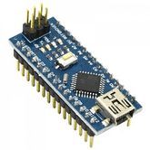
Arduino nano:
STEP 1(Hardware connection):
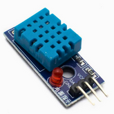
Let us first setup the transmitter part first. The transmitter part contains Arduino Nano Board, DHT11 Humidity & Temperature Sensor and LoRa Module. Assemble the connection between Arduino nano and DHT sensor as shown in the table below:
|
Arduino nano |
DHT11 Sensor |
|
5 v |
VCC |
|
GND |
GND |
|
Digital Pin 7 |
Out |
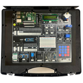
And the connection between Lora and Arduino nano:
|
Lora module |
Arduino nano |
|
2,3,4,5,6,7,8,9 (8 Pin connector) |
Keypad connector (2,3,4,5,6,7,8,9) |
|
4 Pin connector (G, 5V, 10, 11) |
4 Pin connector (G, 5V, 10, 11) |
|
4 Pin connector (G, 5V, 12, 13) |
4 Pin connector (G, 5V, 12, 13) |
read more : Top 10 Arduino Projects to Get Started With
STEP 2(downloading the libraries):
Connect your Arduino nano with DHT11 Sensor. For DHT11 sensor, install the DHT library and for send the sensor readings to Raspberry Pi, install the lora library using the Library Manager in the Arduino IDE. Go to Sketch > Include Library > Manage Libraries and search for library name in the library manager.

STEP 3 (Explanation of the program):
Explanation:
Including the necessary libraries: We include the required libraries, such as LoRa, SPI, and DHT (for the DHT11 sensor).
Defining the constant: The code defines the type and digital pin of DHT sensor and define the required frequency for the Lora module. The ss, rst, and dio0 are the pin numbers used by the LoRa transceiver module that is connected to Arduino nano pin 10, 9, 2.
Note: Frequesncy should be same for both sender and receiver.
Create necessary objects: It defines the DHT sensor object called dht.
Setup Function: The setup function initializes the serial communication, the DHT sensor and the Lora module. It set the pin for lora transceiver using setPins() function. The code waits until LoRa initialization is successful before printing a confirmation message.
Loop Function: The loop function reads the temperature and humidity values from the DHT sensor. Then it prints these values to the serial monitor. After that, it starts a LoRa packet, writes the temperature and humidity values to the packet, and ends the packet transmission.
read more : Top 10 Arduino Projects for Beginners
Sender program:
#include

#include

#include


#define LORA_FREQUENCY 868E6

#define DHTPIN 7 // Digital pin connected to the DHT sensor

#define DHTTYPE DHT11 //DHT sensor type

DHT dht(DHTPIN, DHTTYPE);


//define the pins used by the transceiver module

#define ss 10

#define rst 9

#define dio0 2


void setup() {

  Serial.begin(115200);

  dht.begin();

  while (!Serial);

  Serial.println("LoRa Sender");


  //setup LoRa transceiver module

  LoRa.setPins(ss, rst, dio0);

  while (!LoRa.begin(LORA_FREQUENCY)) {

    Serial.println(".");

    delay(500);

  }

  Serial.println("LoRa Initializing OK!");

}


void loop() {

  float temperature = dht.readTemperature();

  float humidity = dht.readHumidity();


  Serial.print("Temperature: ");

  Serial.print(temperature, 2);

  Serial.print("\t Humidity: ");

  Serial.println(humidity, 2);


  LoRa.beginPacket();

  LoRa.print("Temperature: ");

  LoRa.print(temperature);

  LoRa.print("\t Humidity: ");

  LoRa.print(humidity);

  LoRa.endPacket();

  delay(1000);

}
NOTE: For using the Arduino nano as a receiver, connect Lora module with Arduino nano according to above hardware connection and dowload the required libraries as shown at the start. After that upload the below receiver code.
Nano Receiver :
Explanation:
Including the necessary libraries: We include the required libraries, such as LoRa, SPI, and DHT (for the DHT11 sensor).
Defining the constant: The code defines the type and digital pin of DHT sensor and define the required frequency for the Lora module. The ss, rst, and dio0 are the pin numbers used by the LoRa transceiver module that is connected to Arduino nano pin 10, 9, 2.
read more : Arduino Nano to Server using IOTIF LoRa
Setup Function: It initializes the serial communication, sets up the LoRa module with the specified pins, and configures the LoRa module with the specified frequency. The code waits until LoRa initialization is successful before printing a confirmation message.
Loop Function: It checks if there is a LoRa packet available by calling LoRa.parsePacket(), which returns the size of the packet if one is available. If a packet is received, it prints the message "Received packet '" to the serial monitor. It then reads the contents of the packet using LoRa.readString() and prints the received data to the serial monitor. Lastly, it prints the Received Signal Strength Indication (RSSI) of the packet using LoRa.packetRssi().
Code:
#include
#include
#define LORA_FREQUENCY 868E6
//define the pins used by the transceiver module
#define ss 10
#define rst 9
#define dio0 2
#define BUILTIN_LED 1

void setup() {
  Serial.begin(115200);
  while (!Serial);
  Serial.println("LoRa Receiver");

  //setup LoRa transceiver moduled
  LoRa.setPins(ss, rst, dio0);

  while (!LoRa.begin(LORA_FREQUENCY)) {
    Serial.print(".");
    delay(500);
  }
  Serial.println("LoRa Initializing OK!");
}

void loop() {
  // try to parse packet
  int packetSize = LoRa.parsePacket();
  if (packetSize) {
    // received a packet
    Serial.print("Received packet '");

    // read packet
    while (LoRa.available()) {
      String LoRaData = LoRa.readString();
      Serial.print(LoRaData);
    }

    // print RSSI of packet
    Serial.print("' with RSSI ");
    Serial.println(LoRa.packetRssi());
  }
}
Conclusion
The Arduino Nano Node to Node communication using IoTIF LoRa opens up a world of possibilities for connectivity and data exchange. The Arduino Nano, with its compact size and versatile capabilities, serves as an excellent platform for building innovative IoT projects. The sender program, combined with the Nano receiver code, enables seamless communication between nodes, facilitating the exchange of vital information wirelessly. With LoRa technology at its core, this system ensures long-range transmission and low power consumption, making it ideal for applications such as smart agriculture, environmental monitoring, and industrial automation. Embrace the potential of Arduino Nano and IoTIF LoRa to unlock endless possibilities in the world of IoT. Explore, innovate, and connect like never before!
If you appreciate our work don't forget to share this post and leave your opinion in the comment box.
Please do check out other blog posts about Popular electronics
Make sure you check out our wide range of products and collections (we offer some exciting deals!)


