How to Setup Fingerprint Sensor with Arduino
Summary
Discover the world of biometric technology with our latest blog on "How to Setup Fingerprint Sensor with Arduino." Uncover the magic behind fingerprint sensors, dive into the mechanics of the R307 Optical Fingerprint Scanner, and unveil the components you need. Follow our easy steps to seamlessly integrate the sensor with Arduino, supported by clear and concise code. Get ready to be amazed as we unravel the working principle behind this innovative fusion of hardware and software. Elevate your understanding and embark on a journey of secure identification. Join us in this adventure of digits and data!
Introduction
Discover the potential of adding biometric security systems to your projects with this Introduction to Interfacing Fingerprint Sensor With Arduino. Our comprehensive tutorial will show you how easy it is to implement and integrate a fingerprint identification system into any project or device using an Arduino microcontroller, suitable for both beginners and experienced makers alike
How does a Fingerprint Sensor work?
Fingerprint sensors provide a secure way to identify and authenticate individuals. They work by scanning the ridges of the fingertip, which contains unique patterns like lines that can be used for authentication purposes. Fingerprints are collected using an electronic device, typically one with a small electric current or infrared illumination. This causes tiny differences in electrical potential on areas of common ridge endings and bifurcations – these signals create images called minutiae points that are then analyzed against stored records already associated with each individual's identity such as their signature or other personal information like facial recognition data indexed from previous fingerprint scans taken years before they were born! The resulting image is processed further according to algorithms set up in advance based on what type of verification process needs to occur (e.g., verifying payments). Finally, if all criteria match correctly after comparison between two sets of fingerprints scanned during authentication attempts - access will be granted into secured lockers/doors/software applications etc.. As technology progresses so too do ways we use biometric-based identification systems: this includes improved accuracy due to more complex algorithms; faster processing speeds; greater storage capacity allowing multiple prints per person & even encrypting data at rest for added security measures when needed!
read more : Interfacing Proximity Sensors with Arduino
What is the R307 Optical Fingerprint Scanner?
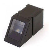
The R307 Optical Fingerprint Scanner is a reliable, secure biometric device designed to meet your authentication needs. It features top-level security protocols and advanced optical fingerprint technology for fast, accurate scanning and identification of users. With its large capacity database memory storage system, it can store up to 1 million user templates while also allowing compatibility with third-party systems through Wiegand input/output ports or standalone communication interfaces such as USB ports. Additionally, the high-resolution imaging allows capturing full fingerprints from one swipe - regardless of size or orientation. This makes sure that only authorized personnel are allowed access while keeping out intruders who don’t have valid credentials stored in the scanner's memory bank. The R307 not only offers unrivalled performance but reliability too thanks to its water-resistant design that ensures consistent operation even in harsh environments ranging from extreme temperatures & dust particles; making it ideal for business applications both indoors and outdoors alike!
Features of Fingerprint Sensor
- Supply voltage: DC 4.2 ~ 6.0V
- Supply current: Working current: 50mA (typical) Peak current: 80mA
- Fingerprint image input time: <0.3 seconds
- Window area: 14x18 mm
- Matching method: Comparison method (1: 1)
- Search method (1: N)
- Characteristic file: 256 bytes
- Template file: 512 bytes
- Security Level: Five (from low to high: 1,2,3,4,5)
- Fake rate (FAR): <0.001%
- Refusal rate (FRR): <1.0%
- Search time: <1.0 seconds (1: 1000 hours, mean value)
- Host interface: UART \ USB1.1
- Communication baud rate (UART): (9600xN) bps Where N = 1 ~ 12 (default N = 6, ie 57600 bps)
- Working environment: Temperature: -20 ℃ - +40 ℃ Relative humidity: 40% RH-85% RH (no condensation)
- Storage environment: Temperature: -40 ℃ - +85 ℃ Relative humidity: <85% H (no condensation)
read more : How 433MHz RF Module Works & Interfacing With Arduino
Pinout of the R307 fingerprint scanner
| Pin number | Name | Type | Function/Description of pin |
| 1 | 5V | Input | Power input |
| 2 | GND | _ | Signal ground |
| 3 | TXD | Output | Data output. TTL logical level |
| 4 | RXD | Input | Data input. TTL logical level |
| 5 | Touch | Output | Finger detection signal |
| 6 | 3.3V | Input | Finger detection power |
Components Required
read more : Interfacing MAX30100 Pulse Oximeter with Arduino
Steps for Setting Up Fingerprint Sensor with Arduino
As mentioned earlier, it is very easy to set up the Fingerprint sensor with Arduino. For this example, we will take the 6 pin variant of the fingerprint sensor. It is also available in 4 and 8 pin variants.
- Download the Adafruit Fingerprint sensor library. https://github.com/adafruit/Adafruit-Fingerprint-Sensor-Library
- Open the .zip file and extract the library folder into the main library folder of your Arduino project. It is usually in the location C:\Users\PC\Documents\Arduino\libraries\
- Moving on to the circuitry, we need to connect 4 wires from the fingerprint sensor to the Arduino. Once identified, connect Vcc to the 5V pin of Arduino. GND to GND of Arduino. TX to digital pin 2 and RX to digital pin
In the 6 wire variant (R307 module), when viewing the connector, the leftmost wire(RED) should be Vcc, the one next(BLACK) should be GND, next(YELLOW) should be TX and the next(WHITE) is RX. The first two wires from the right are not connected.
Note: If you want to power the sensor using a 3.3V supply, make sure you short the jumper labeled 3.3 located right above the main connector. Once this jumper is shorted, you can use the last wire(labeled 3.3V) to power the sensor.
The second last wire from the right (labeled touch) is not generally used in this setup, but its primary function is to give an active low output whenever a touch is there on the sensor by finger.

read more : Interfacing MPU-9250 9-DOF Sensor with Arduino
Fig: Connections for the fingerprint sensor with Arduino. Note- Colors of the wire may vary depending on the sensor module model. Refer to the datasheet in this case.
Once the connections are done, upload the following code into your Arduino and open the serial monitor at 9600 baud.
This code can also be found in the fingerprint sensor library. Open the Arduino IDE, go to file -> Example -> Adafruit Fingerprint Sensor Library -> Enroll.
With the other variants of the fingerprint sensor which may have a different number of connecting wires, you can refer to the datasheet to find which pins are for Vcc, GND, TX, RX.
Code
#include
// On Leonardo/Micro or others with hardware serial, use those! #0 is yellow wire, #1 is white
// uncomment this line:
// #define mySerial Serial1
// For UNO and others without hardware serial, we must use software serial...
// pin #2 is IN from sensor (YELLOW wire)
// pin #3 is OUT from Arduino (WHITE wire)
// comment these two lines if using the hardware serial
#include
SoftwareSerial mySerial(2, 3);
Adafruit_Fingerprint finger = Adafruit_Fingerprint(&mySerial);
uint8_t id;
void setup()
{
Serial.begin(9600);
while (!Serial); // For Yun/Leo/Micro/Zero/...
delay(100);
Serial.println("\n\nAdafruit Fingerprint sensor enrollment");
// set the data rate for the sensor serial port
finger.begin(57600);
if (finger.verifyPassword()) {
Serial.println("Found fingerprint sensor!");
} else {
Serial.println("Did not find fingerprint sensor :(");
while (1) { delay(1); }
}
}
uint8_t readnumber(void) {
uint8_t num = 0;
while (num == 0) {
while (! Serial.available());
num = Serial.parseInt();
}
return num;
}
void loop() // run over and over again
{
Serial.println("Ready to enroll a fingerprint!");
Serial.println("Please type in the ID # (from 1 to 127) you want to save this finger as...");
id = readnumber();
if (id == 0) {// ID #0 not allowed, try again!
return;
}
Serial.print("Enrolling ID #");
Serial.println(id);
while (! getFingerprintEnroll() );
}
uint8_t getFingerprintEnroll() {
int p = -1;
Serial.print("Waiting for valid finger to enroll as #"); Serial.println(id);
while (p != FINGERPRINT_OK) {
p = finger.getImage();
switch (p) {
case FINGERPRINT_OK:
Serial.println("Image taken");
break;
case FINGERPRINT_NOFINGER:
Serial.println(".");
break;
case FINGERPRINT_PACKETRECIEVEERR:
Serial.println("Communication error");
break;
case FINGERPRINT_IMAGEFAIL:
Serial.println("Imaging error");
break;
default:
Serial.println("Unknown error");
break;
}
}
// OK success!
p = finger.image2Tz(1);
switch (p) {
case FINGERPRINT_OK:
Serial.println("Image converted");
break;
case FINGERPRINT_IMAGEMESS:
Serial.println("Image too messy");
return p;
case FINGERPRINT_PACKETRECIEVEERR:
Serial.println("Communication error");
return p;
case FINGERPRINT_FEATUREFAIL:
Serial.println("Could not find fingerprint features");
return p;
case FINGERPRINT_INVALIDIMAGE:
Serial.println("Could not find fingerprint features");
return p;
default:
Serial.println("Unknown error");
return p;
}

Serial.println("Remove finger");
delay(2000);
p = 0;
while (p != FINGERPRINT_NOFINGER) {
p = finger.getImage();
}
Serial.print("ID "); Serial.println(id);
p = -1;
Serial.println("Place same finger again");
while (p != FINGERPRINT_OK) {
p = finger.getImage();
switch (p) {
case FINGERPRINT_OK:
Serial.println("Image taken");
break;
case FINGERPRINT_NOFINGER:
Serial.print(".");
break;
case FINGERPRINT_PACKETRECIEVEERR:
Serial.println("Communication error");
break;
case FINGERPRINT_IMAGEFAIL:
Serial.println("Imaging error");
break;
default:
Serial.println("Unknown error");
break;
}
}
// OK success!
p = finger.image2Tz(2);
switch (p) {
case FINGERPRINT_OK:
Serial.println("Image converted");
break;
case FINGERPRINT_IMAGEMESS:
Serial.println("Image too messy");
return p;
case FINGERPRINT_PACKETRECIEVEERR:
Serial.println("Communication error");
return p;
case FINGERPRINT_FEATUREFAIL:
Serial.println("Could not find fingerprint features");
return p;
case FINGERPRINT_INVALIDIMAGE:
Serial.println("Could not find fingerprint features");
return p;
default:
Serial.println("Unknown error");
return p;
}
// OK converted!
Serial.print("Creating model for #"); Serial.println(id);

p = finger.createModel();
if (p == FINGERPRINT_OK) {
Serial.println("Prints matched!");
} else if (p == FINGERPRINT_PACKETRECIEVEERR) {
Serial.println("Communication error");
return p;
} else if (p == FINGERPRINT_ENROLLMISMATCH) {
Serial.println("Fingerprints did not match");
return p;
} else {
Serial.println("Unknown error");
return p;
}

Serial.print("ID "); Serial.println(id);
p = finger.storeModel(id);
if (p == FINGERPRINT_OK) {
Serial.println("Stored!");
} else if (p == FINGERPRINT_PACKETRECIEVEERR) {
Serial.println("Communication error");
return p;
} else if (p == FINGERPRINT_BADLOCATION) {
Serial.println("Could not store in that location");
return p;
} else if (p == FINGERPRINT_FLASHERR) {
Serial.println("Error writing to flash");
return p;
} else {
Serial.println("Unknown error");
return p;
}
}
Working
The sensor will first display if the sensor is detected or not. If not detected, make sure the connectors are not loose and reset the Arduino. Once detected, it will ask you to enter a unique ID number between 1-127. Choose a number and hit enter. The sensor will then prompt you to repeatedly lift and place your finger to register the image. If you choose the same number twice, the fingerprint data will be overwritten by the new one.
read more : IR Sensor Interfacing with Arduino
Conclusion:
In a world where security and technology intersect seamlessly, the integration of fingerprint sensors with Arduino emerges as a fascinating innovation. By unraveling the intricacies of these biometric marvels and exploring the capabilities of the R307 Optical Fingerprint Scanner, we've unlocked a realm of possibilities. Armed with the knowledge of essential components and guided through the setup steps, you're now poised to embark on your fingerprint sensor journey. With code as your compass and understanding its working as your beacon, you're ready to infuse your projects with a touch of cutting-edge security. Step into the future today – where your unique identity meets the power of Arduino.
Frequently Asked Questions
1. What is TX and RX in fingerprint sensor?
TX and RX in a fingerprint sensor is the key component to storing, verifying, and authenticating finger information. TX stands for transmission while RX refers to reception; together they allow data input from an external device such as a scanner or camera into your computer systems through secure connections. This technology helps create foolproof identification platforms by recording accurate images of fingerprints which can be used for authentication purposes with accuracy far superior than traditional methods like passwords. The use of this cutting edge technology makes sure only authorized personnel have access to sensitive areas and ensures customers satisfaction infor personal security applications.
read more : How to connect ZMPT101B to Arduino
2. How does fingerprint sensor work with Arduino?
Fingerprint sensors are a fantastic way for Arduino users to securely access their projects. Utilizing this technology allows an individual to give their project the highest level of security without requiring them to remember any passwords or pins.
Combining fingerprint recognition and Arduino opens up potential in home automation, biometrics security systems, authenticated payments, and more! Fingerprints can be used as user identity authentication with maximum accuracy; no two fingerprints are alike so it ensures secure access is only given when needed.
The process starts by scanning your finger on the sensor which then converts it into digital data that will match against stored prints within its database. Once matched correctly some simple programming code will trigger whatever action was set out - like unlocking doors or turning lights off/on etc... Depending on what needs doing different types of fingerprint readers may be required such as optical scanners (often found at airports), capacitive scanners (used mostly for mobiles) and ultrasonic variants devices too – all work differently but do essentially achieve the same result: verifying identities based solely on unique physical traits.
Using a combination of hardware components including specific controllers from manufacturers like Adafruit Industries Inc., along with open-source libraries available online makes connecting fingerprint sensors easy with minimal coding knowledge necessary – making interactive applications accessible even if you’re not familiar with working directly with complex microcontrollers yourself!
read more : Arduino VS NodeMCU
3. Which interface is used by fingerprint sensor?
Biometric fingerprint sensors provide a secure and reliable means of authentication, simplifying the user experience. This technology uses interface modules to capture minutiae from fingerprints in order to identify users accurately. The majority of fingerprint sensor hardware is available in USB or serial connection interfaces with mobile-capable options for tablets and smartphones as well – such as UART/USB-based readers integrated into back covers on some models. Capacitive individual finger scanners are also becoming increasingly popular due to their convenience and superior accuracy levels compared with optical counterparts; this type usually functions via an RS232 or I2C protocol format.. Many devices offer optional support for additional communication protocols, including SPI 2 wire, and Wiegand & CAN bus Interfaces too which give you much more flexibility when integrating the system into existing infrastructures like Access Control Management systems (ACMS).
read more : Which Arduino Board to Buy
Combining fingerprint recognition and Arduino opens up potential in home automation, biometrics security systems, authenticated payments, and more! Fingerprints can be used as user identity authentication with maximum accuracy; no two fingerprints are alike so it ensures secure access is only given when needed.
The process starts by scanning your finger on the sensor which then converts it into digital data that will match against stored prints within its database. Once matched correctly some simple programming code will trigger whatever action was set out - like unlocking doors or turning lights off/on etc... Depending on what needs doing different types of fingerprint readers may be required such as optical scanners (often found at airports), capacitive scanners (used mostly for mobiles) and ultrasonic variants devices too – all work differently but do essentially achieve the same result: verifying identities based solely on unique physical traits.
Using a combination of hardware components including specific controllers from manufacturers like Adafruit Industries Inc., along with open-source libraries available online makes connecting fingerprint sensors easy with minimal coding knowledge necessary – making interactive applications accessible even if you’re not familiar with working directly with complex microcontrollers yourself!


