Nodemcu esp8266 projects for beginners
Summary
This blog post introduces beginners to the NodeMCU ESP8266, a beginner-friendly development board ideal for IoT projects. It begins with an overview of the board's relevance in DIY electronics, followed by a detailed look at its features and specifications, such as WiFi capability and processor speed. The post outlines several starter projects like home automation and weather stations, providing simple steps for each. It concludes by encouraging newcomers to explore the versatile and educational opportunities offered by the NodeMCU ESP8266, making it a perfect gateway into the world of IoT.
What is Nodemcu esp8266?
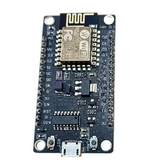
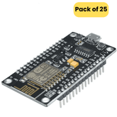
The ESP8266 Wi-Fi SoC chip has an open-source development environment and firmware called NodeMCU ESP8266. It has an integrated 802.11b/g/n Wi-Fi transceiver, 4 MB of Flash memory, and 128 KB of RAM. For Internet of Things applications, NodeMCU enables you to write Arduino-compatible sketches directly on the ESP8266. The ESP8266 Wi-Fi SoC chip has an open-source development environment and firmware called NodeMCU ESP8266.
It has an integrated 802.11b/g/n Wi-Fi transceiver, 4 MB of Flash memory, and 128 KB of RAM. For Internet of Things applications, NodeMCU enables you to write Arduino-compatible sketches directly on the ESP8266.
Specifications
- Microcontroller: Tensilica 32-bit RISC CPU Xtensa LX106
- Operating Voltage: 3.3V
- Input Voltage: 7-12V
- Digital I/O Pins (DIO): 16
- Analog Input Pins (ADC): 1
- UARTs: 1
- SPIs: 1
- I2Cs: 1 • Flash Memory: 4 MB
- SRAM: 64 KB
- Clock Speed: 80 MHz
- Additionally, it comes with a USB-TTL interface based on CP2102 for easy plug-and-play connectivity.

ESP8266 Projects for Beginners
-
Flashing NodeMCU on Esp8266 and Getting Started
A simple beginning, the aim of this project is to learn how to lash NodeMCU on esp8266 v1. Components Needed would be USB to TTL converter,esp8266 , Male to Male (2x) and Male to Female(6x) Connecting Wire and a Bread Board.

In this project you will learn the steps to flash NodeMCU firmware onto an ESP8266 v1 module using a USB to TTL converter and establish hardware connections, uploaded the firmware, and communicated with the ESP8266 via a serial terminal.
-
Getting Started with ESP8266 and Arduino
This project is about getting started with Esp8266 WiFi Module and how the ESP8266 Arduino pair can be used in IoT Projects.

In this project, we will be using the Ai-Thinker’s ESP-01 Module.
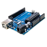
It consists of 8 pins, involves interfacing the ESP8266 WiFi Module with Arduino and uploading our own program. All you need are Arduino UNO ,ESP8266 ESP-01, 1 KΩ Resistor , 2.2 KΩ Resistor, 100 pF Capacitor (Capacitor Code – 104) , Mini Breadboard , Connecting Wires With simple connections and a code you can see how the ESP8266 Arduino Interface will work, how to upload a program into the ESP8266 WiFi Module and access the Input/Output Pins of the ESP8266 Module.
-
How to Update Flash ESP8266 Firmware
This is the project on ESP8266 and in this project, I’ll show you how to flash the Official Espressif Firmware in ESP8266 using Arduino. This project can also be used if you want to update to the latest ESP8266 Firmware.
Components needed for this project are Arduino UNO ,ESP8266, 1 KΩ Resistor, 2.2 KΩ Resistor, Push Button, SPDT Switch, Connecting Wires and Mini Breadboard.

Connection:
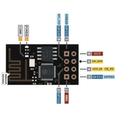
- VCC to 3.3V
- GND to GND
- TX to TX of Arduino UNO
- RX to RX of Arduino UNO (through level converter)
- GPIO0 to GND
- RST to GND through Push Button
- CH_PD to 3.3V
In Arduino IDE, select the correct COM Port and open the Serial Monitor. Set the baud rate to 115200 and select Both NL and CR option in the serial monitor. After this press the RST Button of the ESP8266 for a second and release.
The ESP8266 Module will reset and display “ready” after some garbage data on the serial monitor. In order to check for the firmware version, you need to type the following AT Command and hit send.
This command will return the firmware version of the ESP8266 Module. All the AT Commands should be in Upper Case There are two types of SDK or Software Development Kits for ESP8266: Non-OS SDK and RTOS SDK. The Non-OS SDK, as the name suggests, isn’t based on any OS. Using this SDK, you can compile IOT_Demo and AT Commands. The RTOS SDK on the other hand is based on FreeRTOS.
In order to flash the firmware in ESP8266, first open the Flash Download Tool or the Flasher Software of ESP8266. At the time of working on this project, I have the version 3.6.2.2.
So, open the application file ESPFlashDownloadTool_v3.6.2.2. You will then get various options like ESP8266 Download Tool, ESP8285 Download Tool, ESP32 Download Tool and ESP32D2WD Download Tool.
Select the ESP8266 Download Tool. efore starting the flashing, check that GPIO0 is connected to GND and give a pulse LOW (push the Reset button) on the RST pin. By the end of this project you would have seen how to update/flash firmware in ESP8266 Module using the official Espressif ESP8266 Firmware.
-
Control a Relay using ESP8266 and Android MIT App Inventor
The this project in the ESP8266 WiFi Module Series is to Control a Relay using ESP8266 and Android through an App (Application) developed with the help of MIT App Inventor. By installing this App in your Android Phone, you can control a relay using ESP8266 that is connected to the same WiFi network as your phone.

Components Required
- ESP8266
- Arduino UNO
- Resistors (1KΩ and 2.2KΩ) – both are ¼ Watt Resistors
- Jumper Wires
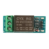
- Relay Module
- Small 5V Bulb
- Push Button
- SPDT Switch
- Android App
- Android Phone
- Computer with Internet
You will have to download the app and set it up After creating a new project, you will see a screen on which you can layout different objects like Buttons, Sliders, Textbox, etc. Create an interface similar to the one shown below. It consists of three Buttons few Labels and a Web Component.
In order to control a Relay using ESP8266, A code is responsible for connecting the ESP8266 WiFi Module to the specified WiFi Network, assigning a Static IP Address to the ESP8266 Module, creating a simple HTTP Server on ESP8266 and also listen to clients.
In this project, we have seen how to control a relay using ESP8266 through WiFi with the help of an Android App developed using MIT App Inventor 2 Application. Such projects can be the stepping stone for complex home automation system, where the maker can not only assemble the circuit but also make his own Android Application. The next big step of this project would be controlling the relay from anywhere in the World.
-
Connect ESP8266 to ThingSpeak
ThingSpeak is different and special as it uses simple HTTP Protocol to transfer, store and retrieve information from different sensors also has support from MATLAB. The close relationship between ThingSpeak and MATLAB has lead to integrate several key features of MATLAB into the ThingSpeak Application. You will have to create a Thing’s speak channel and make that your test channel.
Connect the Arduino board to the computer and open serial monitor , to check the connection use AT command , once connected you can upload your code. the Arduino will establish TCP connection to the ThingSpeak API and transmits the random number for every 5 seconds and this data can be monitored in the ThingSpeak API Website.
In this project you will learn how to connect ESP8266 to ThingSpeak API using both the direct AT Commands as well as through Arduino. Using the ThingSpeak API, you can monitor sensor data from anywhere in the World. Most frequently used sensors are DHT11 Humidity and Temperature Sensor, DS18B20 Temperature Sensor and LM35.
-
How to Enable ESP8266 Deep Sleep Mode
In this experiment we will lean about the Low Power operations of ESP8266 SoC and also learn how to enable ESP8266 Deep Sleep Mode. We will also measure the current for both normal operation mode and Deep Sleep Mode. One of the major factors in selecting an MCU for your product design is its ability to operate in low power mode, a special power management feature of modern Microcontrollers. With its advanced power management technology, the ESP8266EX Wi-Fi SoC supports four different operating modes.
- Active Mode
- Modem–Sleep Mode
- Light–Sleep Mode
- Deep–Sleep Mode
To implement automatic timer-based wake-up from Deep Sleep mode, all you have to do is connect the GPIO16 Pin to the RST Pin. On NodeMCU board, GPIO16 is labeled as D0.

And upload a simple code When the ESP8266 MCU enter deep sleep mode, the LED will turn OFF. After the 5 second sleep time elapses, the GPIO16 pin will reset the MCU through RST pin and the process repeats.
Conclusion:
The ESP8266, with its compact design and powerful features, is an excellent choice for IoT enthusiasts. Whether you’re a beginner or an experienced developer, these projects provide a solid foundation for exploring its capabilities.


