DIY IR SENSOR
In this blog, we will build a simple IR sensor and learn more about the components used in it.
What is a sensor?
A sensor is a device that can quantify the environment and produce some corresponding output. For our case, the output will be in the form of an electrical signal which we can measure, modify according to our requirements and drive components on it.
Also, read our blog on the What Is IR Sensor explaining what is IR sensor, how it works, and the application of IR sensors
IR rays
IR (Infrared Radiation) often called Infrared Light is a part of the Electromagnetic Spectrum that has a wavelength of the order of 700 nm to 1 mm. It is invisible to the naked light as it doesn’t coincide with the visible spectrum.
Components Required and their Information:
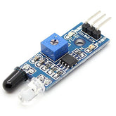
- Phototransistor
- IR LED
- 100 Ohm Resistor
- 10k Ohm Resistor
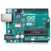
- Arduino Uno
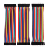
- Jumper Wires
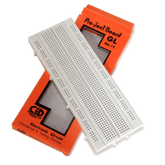
- BreadBoard
Phototransistor:
Are small semiconductor devices that can detect the amount of incident (light) radiation on them and correspondingly alter the current between the emitter and collector.
A photodiode can be used for the same purpose, however as phototransistors are more sensitive, we will be using them.
A transistor has 3 leads - Base, Collector, and an Emitter, However, if you look at the image of a Phototransistor, you will see only 2 leads. That is because the Base is left open here.
IR Led:
An IR led is a small device that emits IR light. Its construction is very simple to a traditional Light Emitting Diode (LED), however as the light emitted by it is in the infrared region, it’s invisible to us.
These are very cheap and used extensively as they are a reliable source of IR light, hence one can see their application in electronics, remote control for T.V., etc.
Also learn how Infrared Sensors detect motion and heat.
Working Principle:
- The IR LED will generate IR rays when given power.
- These infrared rays will travel to a surface or a boundary and then be reflected.
- The reflected rays will fall on the phototransistor and a small number of current flows between the emitter and the collector.
- This can be measured with the help of a microcontroller like Arduino UNO and a voltage divider network.
Also, read our blog on the Working of IR Sensor detailing what is IR sensor, how they works, and the different types of IR sensors.
The circuit diagram and explanation:
- First, we connect one lead of the 100 Ohm resistor to the anode (+ve) of the LED.
- Then we connect the other lead to the 5-volt pin on the Arduino.
- Next, connect the cathode (-ve) of the LED to the ground pin on the Arduino.
- Similarly, we will connect 1 lead of the 10 kilo Ohm resistor to the collector (-ve) of the phototransistor and connect the other lead to the 5-volt pin on the Arduino.
- And connect the emitter (+ve) of the phototransistor to the ground pin on the Arduino.
- At the junction of the phototransistor and the 10 kilo Ohm resistor, we will make a connection and give it to the A0 pin on our Arduino.
- This completes our connection.
Arduino Code:
/*
* Name: DIY IR sensor code
* Description: A simple code to access the values of your sensor
* Contributor: Jatin Vira
*/
#define InputPin A0 //This is the pin where your Sensor is connected
void setup() //Will be executed only once
{
pinMode(InputPin, INPUT); //Using PinMode function to declare the A0 pin as an Input Pin
Serial.begin(9600); //Setting the Baud Rate to 9600
}
void loop() //Will be executed again and again indefinitely
{
//Create a Variable called SensorValue to store the value from Sensor
int SensorValue = analogRead(InputPin); //Use analogRead to take input from A0 pin
Serial.println(SensorValue); //Serial Printing the stored value on a new line
delay(10); //Setting the delay to 10ms, Experiment with different values and see what it does
}
You can also try using the digitalRead function and see how it affects the sensor values.
Output:
- First, we will upload the code to our Arduino.
- Next, we will open the Serial Plotter in the tools section.
- When you move the hand closer to the sensor you can notice that the value received by the sensor decreases.
- Similarly, when the hand is taken further away from the sensor, the value retrieved goes up.
Applications:
- This can be used as a proximity sensor, which finds use in many areas such as home automation, mobile robots, etc.
- This can be used to differentiate between different colors and subsequently be used in a line following a robot.
This blog has been submitted by VCET Robotics Club, VCET Vasai under the Robocraze Club Outreach Program.


