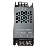
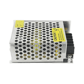
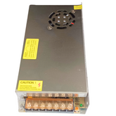
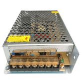
All ABOUT SWITCHED MODE POWER SUPPLY (SMPS)
Summary
Technology has become an integral part of modern society. As a result, it's important to understand the different components and how they interact with each other in order to build efficient systems and products. One of these components is the Switch Mode Power Supply (SMPS). This piece of technology is used to convert electrical power from one voltage level to another while regulating current consumption and ensuring that there aren't any sudden voltage drops or spikes. In this post, we will look at what exactly an SMPS is, its working principle and the various types available in the market today.
Introduction
Switched Mode Power Supply (SMPS) is a type of power supply unit that helps convert low voltage AC electricity from the electrical wall socket, into higher DC voltages for use by electronic equipment. An SMPS is highly efficient and small in size compared to other types of power supplies. This makes them ideal components when designing or building compact electronics devices such as tablets, laptops or embedded systems.
The cost-effectiveness and high efficiency ratio can also help reduce energy costs overtime, which has become an essential factor in today’s working environment where consumers are looking at ways to decrease their carbon footprint. With more advanced features like soft start technology; sophisticated circuit designs improve heat dissipation while keeping noise levels down during operation as well improved overload protection making it safe even with fluctuation network input conditions - this versatile piece of hardware should be top on list for any technologically minded digital device user!
Switched Mode Power Supply (SMPS) is a type of power supply that uses advanced circuitry technology to convert AC voltage into DC, allowing it to run efficiently and at much higher voltages than standard transformers. Its components include transistors, diodes, integrated circuits and printed circuit boards which are controlled by digital logic methods. SMPS use pulse-width modulation method for energy regulation along with other features such as overvoltage protection or overload detection system.
With the help of these state-of-the-art technologies they require very little maintenance compared to conventional transformers for their efficient operation in various applications like TV sets, computers etc. Additionally they save more space than traditional transformer units due to its smaller size & weight making them ideal option for custom installations where specific component requirements need met without sacrificing portability or convenience.
What does SMPS mean?
Switched Mode Power Supply is a converter. Switching devices at higher frequencies and storage components like capacitors or inductors are used to convert the power. It is used as an AC to DC converter and for power efficiency instead of a Linear Power Supply (LPS).

The Linear Power Supply (LPS) is a regulated power supply that losses a lot of power in the form of heat through a series resistor to control the output voltage, resulting in minimal ripple and noise. A linear power supply has a worse energy efficiency (40 - 50%) since it needs larger semiconductor devices to manage the output voltage and produces more heat. So, to reduce the heat and improve efficiency ‘Hewlett Packard’ used an SMPS in its first pocket calculator.

An SMPS converts the voltage and current characteristics as it distributes power to DC loads like personal computers from a DC or AC source (often mains power; see AC adapter). In contrast to a linear power supply, a switching-mode supply's pass transistor alternates between full-on and full-off states with low dissipation and spends comparatively less time in transitions with high dissipation, minimizing wasted energy. In an ideal switched-mode power supply, there is no power loss. The ratio of on-to-off time can be changed to control voltage (also known as duty cycles). A linear power supply, in contrast, controls the output voltage by continuously releasing power from the pass transistor. A key benefit is the greater electrical efficiency of the switched-mode power supply.
Comparison between LPS and SMPS
|
Linear Power Supply (LPS) |
Switched Mode Power Supply (SMPS) |
|
Linear Power Supply consists of linear regulators like LM7805 |
Switched Mode Power Supply consists of switching regulators like MOSFET and transistors. |
|
It only stepdown and produce the output voltage in linear mode |
It supplies the power by switching of series of transistors in the cut off and saturation region. |
|
Low Power factor |
The Medium power factor can reduce by adding a series of capacitors |
|
Reliable than the SMPS |
Reliability depends on the transistor used |
|
Very poor efficiency than the SMPS |
Better efficiency than LPS |
|
The Complexity of the design is low |
The Difficulty in the design |
|
The Weight of the device is more |
Light-weight |
Switched Mode Power Supplies are complex. The key benefit of this increased complexity is stabilised designs made possible by switched mode operation, which may provide more power for a given size, price, and weight of power unit. The AC is rectified and smoothed by a reservoir capacitor when the input is the AC mains (line) supply before being processed by what is essentially a DC-to-DC converter to generate a regulated DC output at the desired level. Therefore, an SMPS can be used in many different battery-powered systems to convert DC to DC, either step up or step down, or AC to DC, such as in a desktop computer power supply.
Blog diagram and working of SMPS

AC Input: Without utilising a transformer, the rectifier and filter circuit combination receive the 50 Hz AC input supply signal directly. That AC input sends to the rectifier bridge.
Switch: In this portion, a fast-switching device, such as a MOSFET or Power transistor, is used. It switches ON and OFF in response to fluctuations, and its output is connected to the primary of the transformer located in this section.
Output Stage: To obtain the necessary DC voltage, the output signal from the switching portion is once more rectified and filtered. The control circuit receives this regulated output voltage.
Control circuit: The signal is picked up by the output sensor, which connects it to the control system. Any rapid spikes shouldn't harm the circuitry because the signal is segregated from the other section. The signal and a reference voltage are both sent as one input to the error amplifier, a comparator that compares the incoming signal with the necessary signal level.
Classification of SMPS
SMPS is classified into two types:
- Non-isolated Topology 2. Isolated topology
Non-isolated Topology
|
Type |
Energy storage |
Feature |
|
Buck |
Single inductor |
o/p I continuous |
|
Boost |
Single inductor |
i/p i is continuous |
|
Buck - Boost |
Single inductor |
Both i/p and o/p I discontinuous |
|
Split - pi |
2 inductors and 3 capacitors |
Bidirectional power control |
|
cuk |
Capacitor and two inductors |
Both i/p and o/p I continuous |
|
Sepic |
Capacitor and two inductors |
i/p i is continuous |
|
Zeta |
Capacitor and two inductors |
o/p i is continuous |
|
Switched Capacitor |
Capacitors only |
No magnetic storage is needed |
The Buck converter Circuit has a transistor with a flywheel circuit (Dl, L1 and C1). The inductor L1 is used to conduct current through the load while the transistor is turned on. Any inductor's activity opposes variations in current flow and serves as an energy reserve. In this instance, the inductor stores energy taken from the increasing output; this energy is later released back into the circuit as a back e.m.f. as the current from the switching transistor is quickly switched off, preventing the switching transistor output from increasing immediately to its peak value.
It is a DC-to-DC power converter that steps up the voltage from its input (supply) to its output while stepping down current (load). This type of switched-mode power supply (SMPS) has at least two semiconductors (a diode and a transistor) and at least one energy storage component, such as a capacitor, inductor, or both. To reduce voltage ripple, filters built of capacitors are typically attached to such a converter's input (load-side filter) and output (occasionally in conjunction with inductors) (supply-side filter). Since boost converters are extremely nonlinear systems, a range of linear and nonlinear control approaches have been investigated to achieve good voltage regulation with significant load changes.
Isolated Topology
|
Type |
Energy Storage |
Feature |
|
Fly back |
Mutual inductor |
isolated form of the buck-boost converter |
|
Ring Choke Converter |
Transformer |
The low-cost self-oscillating flyback converter |
|
Half-forwarded |
Inductor |
Easy to increase or decrease the o/p Voltage |
|
Forward |
Inductor |
Isolated form the of buck converter |
|
Resonant forward |
Inductor and capacitor |
Resonant at a fixed frequency |
|
push-pull |
inductor |
|
|
Half bridge |
Inductor |
|
|
Full bridge |
inductor |
Very efficient use of a transformer, used for highest powers |
|
Isolated cuk |
2 inductors and 2 capacitors |
Perhaps the most popular isolated topology is the flyback. Typically, it is used in low-cost, low-power applications. In addition to the transformer, the flyback topology only needs one active switch and no additional output inductor. As a result, the topology is simple to utilise and inexpensive. Due to the single-ended architecture and the large input and output ripple currents, additional capacitors are needed at both the input and the output.
A full bridge converter is one of the often-employed types that provides isolation in addition to stepping up or down the input voltage. Other capabilities might include switching the polarity and delivering numerous output voltages at once.
Discover budget-friendly SMPS Price deals.
Advantages of SMPS:
- The effectiveness is between 85 and 95 per cent.
- Less power is wasted, and less heat is produced.
- Reduced harmonic feedback
- Compactable size and portable.
- Low Manufacturing cost
- having the capability of providing the required voltage
Disadvantages of SMPS:
- Switching at high frequencies causes the noise to exist.
- The circuit is complicated to analyse.
- electromagnetic interference is produced.
Conclusion
In this blog post, we have learnt that SMPS (Switch Mode Power Supply) is an essential aspect of modern electronics and technology. Understanding the meaning and functioning of SMPS, as well as comparing it with LPS (Linear Power Supply) and exploring its classification and advantages, can help you make informed decisions when it comes to powering your devices. Whether you are an electronics enthusiast or a professional, staying informed about SMPS is crucial to stay ahead in the game. So, don't wait any longer, dive into the world of SMPS and take advantage of its numerous benefits!
If you appreciate our work don't forget to share this post and leave your opinion in the comment box.
Please do check out other blog posts about Popular electronics
Make sure you check out our wide range of products and collections (we offer some exciting deals!)
Excerpt
Frequently Asked Questions
1. What is SMPS explain in detail?
This abbreviation stands for Switching Mode Power Supply, a phenomenon where transistors are utilized in a non-linear manner to regulate the transformation of electrical energy. This methodology is widely sought after, for its impressive efficiency and compact form factor, rendering it suitable for use in a plethora of electronic devices ranging from the minuscule smartphone to the gargantuan gaming console. SMPS operates by engaging in a frenetic switch of electrical energy, on and off, at a frequency that is high enough to induce a mystical and captivating aura. The result of this pulsating behavior is a device that is smaller, lighter and more efficient in design compared to its linear counterparts, truly a marvel of modern technology.
2. Is SMPS DC or AC?
SMPS, or the Switch Mode Power Supply. A brilliant piece of engineering that harnesses the power of switching technology to transmute AC voltage into low-frequency DC voltage with regulation, effectively functioning as an AC-to-DC converter.
3. What are the advantages of SMPS?
The Switched-mode power supplies, also known as SMPS, exhibit a plethora of perks in comparison to the conventional linear power supplies. Their higher efficiency, miniaturized size, lightweight build, and the capability to regulate the output voltage are some of their prime attributes. These SMPS also have the astoundingly remarkable ability to transmute AC power into the DC power that is so indispensable for electronic devices, thereby rendering them an ubiquitous choice for applications requiring both exceptional efficiency and voltage regulation. The SMPS boast a stupendous power density, signifying that they are capable of delivering an awe-inspiring amount of power in a diminutive package, thereby making them ideal for portable electronic devices and other applications that are constricted by space.
4. What is a switched mode power supply (SMPS)?
A switched mode power supply (SMPS) converts electrical power efficiently by switching the input voltage on and off rapidly. This method allows for size and weight reduction compared to traditional power supplies. SMPS units are widely used in various electronic devices, providing stable voltage with high efficiency.
5. How does SMPS differ from a linear regulator?
SMPS differs from linear regulators mainly in efficiency and size. While linear regulators dissipate excess voltage as heat, SMPS units use high-frequency switching to regulate output voltage, resulting in less heat and greater efficiency. This makes SMPS ideal for powering sensitive electronics and compact devices.
6. What are common types of SMPS (buck, boost, flyback)?
Common types of SMPS include buck, boost, and flyback converters. Buck converters step down voltage, boost converters step up voltage, and flyback converters provide isolation while converting voltage. Each type serves specific applications, maximizing efficiency and performance in electronic devices.
7. What’s the working principle behind an SMPS?
The working principle of an SMPS involves converting input AC or DC voltage into a desired output through high-frequency switching. A transformer, inductor, and capacitors smooth the output voltage. Feedback mechanisms ensure stable operation, adapting to varying loads and ensuring high efficiency in conversion.
8. Where are SMPS units commonly used in electronics?
SMPS units are commonly found in computers, TVs, and mobile chargers because of their compact size and efficiency. They are also used in LED lighting, industrial equipment, and consumer electronics, making them essential for modern electronic systems.
9. What are advantages of SMPS over traditional power supplies?
The advantages of SMPS over traditional power supplies include higher efficiency, reduced size, and lighter weight. SMPS designs allow for better thermal management and lower energy consumption, making them ideal for applications where space and energy efficiency are critical.
10. What are common design considerations for SMPS circuits?
Key design considerations for SMPS circuits include input and output voltage levels, load conditions, component selection, and thermal management. It's also crucial to account for electromagnetic interference (EMI) and ensure that the design meets safety and regulatory standards for optimal performance.
11. How do you troubleshoot an SMPS circuit?
Troubleshooting an SMPS circuit involves checking input voltage, output voltage levels, and component integrity, such as diodes and capacitors. Look for signs of overheating and ensure proper connections. Oscilloscope measurements can help identify switching issues and signal anomalies, guiding effective repairs.
12. What safety precautions should you take when designing SMPS?
When designing SMPS, ensure to follow safety precautions like using appropriate fuses, thermal protection, and proper isolation techniques. Considerations for high-voltage areas, proper grounding, and EMI shielding are vital. Always adhere to safety standards and regulations to prevent hazards.
13. What components are critical in an SMPS (inductor, MOSFET, diode, controller)?
Critical components in an SMPS include inductors for energy storage, MOSFETs for switching, diodes for rectification, and controllers for regulating operations. These components work together to manage efficiency and performance, making them essential for reliable power supply design.


